diy solar

diy solar

Please advise a true NEWB on 24V system

Well, I was assuming the BMS on the battery (provided by BigBattery), which is supposed to disconnect at 20V, would suffice.

You will almost certainly disconnect when your weakest cell hits 2.5 volts before the pack hits 20 volts.
Also discharging until one cell is dead empty will tend to destroy your top balance.
Finally and most important...
If the bms is fet based, disconnecting under significant load will be very hard on the bms.
Fet based BMSs can fail closed which means you won't know its not working until your cells get destroyed.
If the bms uses a contactor its not so bad but still pretty hard on the contactor.

Anyway the bms is generally considered to be your reserve parachute.
 
StepandWolf,

Thank you for your suggestions. I figured I may need about 40A DC such as yourself, but wanted a little headroom just in case, so I went 70A for my converter.

1. I don't have a master battery disconnect. The BigBattery does have a built-in power button on the external case which I assumed would function the same.
2. I did not think about a breaker between panels and SCC, but will do that now, thanks for the suggestion! Can you include a pic of your setup, I don't quite understand.
3. Yes, a shunt/meter is next on my list!
4. No shore power connection as I did not anticipate needing that, if at all.
5. I have a separate AC to DC battery charger, but did not plan to wire it into the plan. Would not even know how.
Disconnect - Don't know how these will be mounted, like in a cabinet. You just want to make sure you can get to the master switch in a hurry if need be.

Panel to SCC breakers - I bought this box breaker box and these breakers. The box is rated for outside, but is used a lot inside. In my case, the box keeps me from accidentally bumping the breakers. Also, that box is made for four breakers. I intend to have a second set of panels with their own SCC so I will have four wires coming through my breakers. You don't need the box or that style of breaker, but some method of doing a panel disconnect is suggested, and some say is code, although I don't know if your RV will ever get a electrical inspection :)

My setup is going into a travel trailer with existing shore power which currently goes to the trailer's AC panel and a AC/DC battery charger. I will be disconnecting their shore power wiring and will run new wiring that will go first to the inverter, and from the inverter back to the AC panel.

When I looked at the cost of an ATS, battery charger, and inverter, I thought buying the Victron with them all integrated made a lot of sense plus the name recognition of Victron.

What I like about the Victron, is it magically manages all the power stuff, i.e. it can mix shore power and inverter power so you can actually craw both. I like having the ATS function so I don't need to worry about connecting and disconnecting stuff when connected to shore power.

BTW, I am on version "I" of my drawing and I am still making changes :)
 
You will almost certainly disconnect when your weakest cell hits 2.5 volts before the pack hits 20 volts.
Also discharging until one cell is dead empty will tend to destroy your top balance.
Finally and most important...
If the bms is fet based, disconnecting under significant load will be very hard on the bms.
Fet based BMSs can fail closed which means you won't know its not working until your cells get destroyed.
If the bms uses a contactor its not so bad but still pretty hard on the contactor.

Anyway the bms is generally considered to be your reserve parachute.
If the BMS is a reserve parachute, what is the preferred low voltage disconnect method?
 
Disconnect - Don't know how these will be mounted, like in a cabinet. You just want to make sure you can get to the master switch in a hurry if need be.

Panel to SCC breakers - I bought this box breaker box and these breakers. The box is rated for outside, but is used a lot inside. In my case, the box keeps me from accidentally bumping the breakers. Also, that box is made for four breakers. I intend to have a second set of panels with their own SCC so I will have four wires coming through my breakers. You don't need the box or that style of breaker, but some method of doing a panel disconnect is suggested, and some say is code, although I don't know if your RV will ever get a electrical inspection :)

My setup is going into a travel trailer with existing shore power which currently goes to the trailer's AC panel and a AC/DC battery charger. I will be disconnecting their shore power wiring and will run new wiring that will go first to the inverter, and from the inverter back to the AC panel.

When I looked at the cost of an ATS, battery charger, and inverter, I thought buying the Victron with them all integrated made a lot of sense plus the name recognition of Victron.

What I like about the Victron, is it magically manages all the power stuff, i.e. it can mix shore power and inverter power so you can actually craw both. I like having the ATS function so I don't need to worry about connecting and disconnecting stuff when connected to shore power.

BTW, I am on version "I" of my drawing and I am still making changes :)
I wish I could visualize how you used the breakers and box, and your AC panel and AC/DC battery charger. Unfortunately, none of that makes sense to me as I got into this with very minimum knowledge of circuits.
 
I wish I could visualize how you used the breakers and box, and your AC panel and AC/DC battery charger. Unfortunately, none of that makes sense to me as I got into this with very minimum knowledge of circuits.
Right now they are all parts on my workbench. The breakers go in the box, they use a DIN connector and the DIN connector is in the box...that is how physically the breaker fits in the box. Then your two solar wires come into the box to the two breakers, and then the wires continue on to the SCC. If you look at the two links I gave you, you will see the parts....but you can use any breaker that does the same thing.

My AC panel is what came in the trailer...the AC wire will go from the inverter to where the previous shore wire was connected. I am simply "inserting" the solar system into the AC system that exists. Likewise, I got rid of the hitch mount 12V FLA bats as I will be using the converter for my 12V.

I don't have a separate DC charger, it is incorporated into my inverter. The Victron Multiplus is the Automatic Transfer Switch, DC charger, and inverter all in one.

The system I am building is different from yours and I am no expert on this, but I am just sharing what I learned in the process of my design. The other guys helping you know WAY more about this stuff than me. The breaker box and breakers came from this guy:

Explorist Life

Like Will's site, the Explorist site is very detailed and lots of info. The downside, he is total Victron and Battle Born. So with that focus, his diagrams lean that way, so I just take bits and pieces of what he suggests. Just another resource. I have been researching this for at least a year, and as I said, my system is on the workbench in pieces :(
 
Last edited:
I’m not going to claim any superior knowledge here. My observation is that a couple posters answered your questions well but not in the following way.
(The ABYC chart you posted is a good model. It’s based on marine ‘code’ calculation parameters.)

For ‘big load’ 12V DC wiring (inverter load in this case) I have had the habit of oversizing the cables. If 1/0 matches the table, I use 2/0 but fuse to the 1/0 load.
You are 24V so using still works because it sorta creates an ‘oversize’ by default (depending on how you factor for 24V of course- Amps is Amps.)

The main reason I oversize is voltage drop (performance) but with the ‘undersized’ fuse that matches the smaller load/wire you get a nearly ridiculous margin of ‘safety’ in that the wire basically can never fail. For the pizza or two difference in cost that’s one place overdoing it doesn’t have a significant monetary impact. (I also generally upgage the fuse block wiring both pos(+) and neg(-) and fuse based on the smaller wire or expected max load whichever is smaller. The load side of the fuse block I use 18, 16, 14gage as appropriate and fuse according to load. I don’t intentionally oversize small Amp loads but they often wind up oversized cuz I have bulk 14 or 16 but no 18 on hand) <<<Not required but just some thoughts to consider because you’re starting from scratch; now’s the time if you’re ever going to spend less while spending more in case more headroom is someday desired.
 
Last edited:
Smoothjoey, I have no idea what "contactor-based"means, so I guess I will have to find out. My BMS says "BatteryEVO."

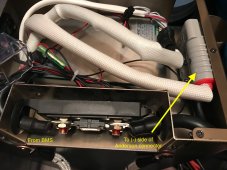
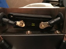
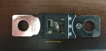
Anyway, I am growing more frustrated because I don't understand why the fuse on my battery is on the lead that leaves the BMS and goes to the negative side of the Anderson connector. I thought fuses were put on positive leads to protect components, so I don't know why the oversized fuse is there in the first place. Also took a while for me to track down an appropriate fuse that would fit the holder that came with the battery (post screws are 2" on center):


Top cover of BigBattery removed, revealing BatteryEvo BMS and black lead from BMS, through 300A fuse and to the negative lead of Anderson connector:

IMG_9677.jpg


Fuse holder (clear plastic cover removed):

IMG_9678.jpg


300A fuse that came with battery. 2" between centers of screw holes:
IMG_9680.jpg
 
Smoothjoey, I have no idea what "contactor-based"means, so I guess I will have to find out. My BMS says "BatteryEVO."

Anyway, I am growing more frustrated because I don't understand why the fuse on my battery is on the lead that leaves the BMS and goes to the negative side of the Anderson connector. I thought fuses were put on positive leads to protect components, so I don't know why the oversized fuse is there in the first place. Also took a while for me to track down an appropriate fuse that would fit the holder that came with the battery (post screws are 2" on center):


Top cover of BigBattery removed, revealing BatteryEvo BMS and black lead from BMS, through 300A fuse and to the negative lead of Anderson connector:


Fuse holder (clear plastic cover removed):


300A fuse that came with battery. 2" between centers of screw holes:
Just more weirdness on the part of the battery manufacturer.
We fuse the positive lead because we ground on the negative by convention.
Its kinda like why we all drive on the same side of the road... except when we don't ;).
A contactor is a big heavy duty dc relay.
I don't see one in your setup.
They usually look like a big metal can with big lugs on it.
 
looks like a 300A ANL fuse. Sometimes they have a slotted hole on one end.

ANL fuse and holder
Hmmm, that link did not work, but the ANL fuses I found are too large for the holder mine came with, but I do see I can buy a separate fuse holder.

I am still very confused....I guess my question is, if I am using the MRBF surface mount block with fuses for each component as pictured (fuse block, inverter, SCC), do I need a fuse on my battery negative terminal? Or, does it matter if it is in fact a 300A fuse?
 
windy nation is a popular provider of components in the industy. this link takes you to the standard ANL holder and your choice of fuses for the amperage you are looking for. But if you have a holder, you only need the fuse if you are trying to change the amperage rating.

Do you have a link to the MRBF block you are referring to.
Weird, that link did not work for me either. But that's ok, I appreciate the enlightenment (serious newb here!!)

For the MRBF, it is this one where I can screw appropriately-rated terminal fuses to the block:

 
I am still very confused....I guess my question is, if I am using the MRBF surface mount block with fuses for each component as pictured (fuse block, inverter, SCC), do I need a fuse on my battery negative terminal? Or, does it matter if it is in fact a 300A fuse?

Yes, you still need a "system" fuse for the battery. The component/wire fuses are there to protect that wire or component. The system fuse protects the battery and everything else.

I use circuit breakers on cables that go to things I may need to turn off, like the solar charge controller. Fuses on wires that go to loads that wouldn't normally ever need to be turned off. That's not a hard and fast rule (for me), but it's where I start when I think of fuses and circuit breakers.
 
Weird, that link did not work for me either. But that's ok, I appreciate the enlightenment (serious newb here!!)

For the MRBF, it is this one where I can screw appropriately-rated terminal fuses to the block:

windy nation anl tested link

Hadn't encountered MRBF. Seems like a spendy, but neat and tidy approach.
 
Yes, you still need a "system" fuse for the battery. The component/wire fuses are there to protect that wire or component. The system fuse protects the battery and everything else.

I use circuit breakers on cables that go to things I may need to turn off, like the solar charge controller. Fuses on wires that go to loads that wouldn't normally ever need to be turned off. That's not a hard and fast rule (for me), but it's where I start when I think of fuses and circuit breakers.
Good to know, thank you!
 
Everything is neat and tidy until you start installing cables. Then it all goes to hell. I had to trade off space for ventilation with space for wire routing. Ventilation won.
 
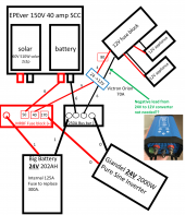
The Victron 24V to 12V converter has 3 terminals: an 18-35V positive input (red), a 0V input (black) and a 10-15V output (red). The instructions are vague, so I called the vendor, Interters are Us, to explain what to do about the single "negative" input. I was told there is no need for the negative lead from my 12V fuse block to the Victron.

Is that correct?Wiring diagram cropped 3.png
 
Back
Top