diy solar

diy solar

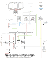
Please check my 7 KW off-grid diagram

jsocolof

New Member
Joined
Jan 20, 2022
Messages
45
I'm in the final stages of designing an off-grid system for a cabin. I would appreciate any feedback on the diagram below, specifically wiring gauges, fuses/breakers, etc. The inverters stack to give 3000W/240V AC split phase at the AC distribution panel. The cable length between the inverters and the batteries will be <5 ft one way. The SCC is rated for 250V/70A DC input and charges at 85A DC. The ground will be a new rod 8' long. I would like to be able to add additional arrays, batteries, SCCs, and/or matched inverters if needed. A new array would serve a new SCC. New inverters would connect to the busbars like the existing ones.

1645925437499.png
 
I'm a pretty big noob, so I'll just put question marks at the end of everything.
Except to say that your diagram is awesome, what software did you use to make this?
As for the diagram, don't you need something heavier than 6 ga coming out of the Charge controller?
Maybe I'm mistaken, but I thought that converted the power down to 48V and it's coming in at 220V with 6 ga...?
 
what software did you use to make this?
This was drawn with Microsoft Visio. I've also used LucidChart for similar drawings, which I think is free maybe?
don't you need something heavier than 6 ga coming out of the Charge controller?
Not a bad observation. The current and voltage (85A/48V nominal) mean it is probably undersized at 6 ga, and when in doubt...
it's coming in at 220V
The charger is set to produce lowest 55.2V during float, and highest 64.8V during equalization. I used the wire sizing chart here: https://www.altestore.com/diy-solar-resources/wire-sizing-tool-for-12-24-and-48-volt-dc-systems/. 6 ga is good for 75A, or a VDI of 12, so it is clearly undersized. The VDI for me for worst case = 20; 2 ga is good for VDI of 31. I think I'll increase it to 2 ga, which is the largest the SCC can take. Thanks for the catch...
 
Yes, the 6AWG from the SCC is too small. The output of the 250/85 is up to 85A. Depending on the length of that wire you want at least 4AWG.

You need a 200A Class T fuse between the battery and positive bus bar (as close to the battery as you can).

The 30A breaker for the 30A generator is too small. You don't want a fuse/breaker the same size as the max normal current because you will get nuisance trips. 40A breaker would be better.
 
Super nice drawing. Couple of comments.
1) Wire and breakers should be matched for ampacity. 6 Ga wire is too small for a 100A breaker. Likewise 2/0 wire is undersized for a 200A breaker. Although welding cable tends to have slightly higher ampacity ratings, consider using Class M cable, very flexible, nice to work with.
2) I would use 200A breakers for the batteries instead of fuses. Fuses can and do wear out simply due to the fact they are the "weak" point in the system by design.
 
6 Ga wire is too small for a 100A breaker. Likewise 2/0 wire is undersized for a 200A breaker.
Marine grade pure stranded copper wire with 105ºC insulation allows 6AWG to be fused up to 130A and 2/0AWG up to 350A.
 
Very nice. One thing that jumps out at me is the battery bank. If I'm reading it right, you have a 48v (nominal) of these https://batteryguys.com/products/crown-deep-cycle-cr-430 At a nominal capacity of 430ah this is about 22kwh, however, at 50% DOD (because they are lead acid) that's only 11kwh of useable battery power.

Based on my experience, a 7kw PV array would do better with a full useable 20kwh battery bank to be able to store/use 100% of the 7kw PV production.

I don't mean this as a criticism, just an observation.
 
There should be a class -t fuse for the battery as close to the battery positive as possible.
The inverter branch circuits should be fused before the disconnect switches, as close as possible to the positive busbar.
Since you are using 2/0 awg wire you can fuse as high as 300 amps assuming you use pure copper wire with insulation rated for 105C
Higher rated fuses typically have less resistance.
6 awg can support a 100 amp over-current protection by aybc and nec free air standards.

Are the Quattro's configured for split phase output?

Since the ac distribution panel has n bonded to g, please ensure that the generator has no neutral/ground bond, also neither inverter must bond n and g when in inverter mode.
I'm sure you know that but thought it was worth saying for others.
 
Great comments from all. Thank you!
You need a 200A Class T fuse between the battery and positive bus bar (as close to the battery as you can).
Will add this. Good catch.

Now I am looking at the wiring through the battery bank to the busbars and from the busbars to the inverters, which I realize is undersized in the drawing. I'm using the calculations from AltE and would appreciate knowing if I've missed anything.

The Quattros are rated at 3000W continuous, 6000W peak, 48V. Looking at one circuit, which let's say can be kept < 10 ft round trip from the Quattro through the busbars and back up to the Quattro, and basing the calculation on the 6000W peak (125A*48V), and using the VDI calculation from AltE:

VDI=(AMPS*FT)/(VOLTAGE DROP*VOLTAGE). Assume a <1% desired voltage drop: VDI=(125*10)/(1*48)=26. From the table, 2 AWG wire looks good. And from the max amperage table, 2 AWG can take 130A, so that works. Couple that with a 130A breaker like this, and are we good to go?

Now for the wiring through the battery bank (bridging the batteries) and to both busbars: This circuit is driving both Quattros, so I'd have to double the current. I believe I can build a battery box that limits the total cable length between busbars to <10 ft:
VDI=(250*10)/1*48)=52. From the table, 1/0 can take the VDI, but it's only good for 170A. I was planning on using 2/0, which is only good for 195A. I would have to use 4/0 cable to be able to accommodate 250A.

1. Am I thinking about the bridge wiring between batteries correctly?
2. Am I right in sizing the wiring for the surge capacity of the inverters?
3. Any feedback on the 130A breaker?

The inverter branch circuits should be fused before the disconnect switches, as close as possible to the positive busbar.
Is this in addition to the fuses/breakers downstream of the disconnects, or in place of?
Since you are using 2/0 awg wire you can fuse as high as 300 amps
I looked at the table at your source, smoothJoey, and it says 2/0 is only good for 300A if it's single-conductor. Am I reading this correctly?
Are the Quattro's configured for split phase output?
Yes
Since the ac distribution panel has n bonded to g, please ensure that the generator has no neutral/ground bond, also neither inverter must bond n and g when in inverter mode.

From the Quattro manual:
The Quattro is provided with a ground relay (see appendix) that automatically connects the N output to the casing if no external AC supply is available.
My casing will be grounded, and I will not be normally operating with an external AC supply, except when running the generator, so each Quattro by default has a G-N bond. This can be disabled. So my choice is not to bond G-N in the AC panel and let the Quattro do the bonding, or to bond in the panel and disable it in the Quattros. Thoughts?
a 7kw PV array would do better with a full useable 20kwh battery bank to be able to store/use 100% of the 7kw PV production.
I agree, however, the issue I have is that I won't have the full 7KW of solar output because the panels are on a barn roof at an 18 degree slope. I was hoping to get one battery bank for starters and see how the charging works for a year and then expand if needed. Initially based on my usage, 10KWh is enough. I've heard, however, that you don't want to mix old and new FLA batteries. If the "old" bank is a year old and I decided to add an identical bank next year, is that not advised? What would be the implications?

This forum is great. I appreciate the help. I will be updating the drawing and will post it after I get through some of these issues.
 
I agree, however, the issue I have is that I won't have the full 7KW of solar output because the panels are on a barn roof at an 18 degree slope.
I have a 13kw PV array where 1/2 is at 25deg and the other 1/2 is 17deg facing South. I off-grid and need a 40kwh battery bank at 80% DOD to be able to consume (thru the night) all the PV power in spring/summer. By 'gross' extrapolation, at 7kw PV (53% of mine) you'll need a 21kwh batter bank at 80% DOD (53% of mine).

You're consumption may be dramatically smaller or larger and you may not have a primary goal of consuming all you produce like I do - but I claim that 'in general' you'll do better with a 20kwh capable battery bank so I'd advise leaving room in your design to get there - and it sounds like you are.

The best thing I've found is to get the system running, gain operational experience and leave room to grow - panels, batteries, equipment. You're in the ballpark for sure. After running things for a while, it will become much clearer how to adjust/expand to suite your needs. :)

I was hoping to get one battery bank for starters and see how the charging works for a year and then expand if needed. Initially based on my usage, 10KWh is enough. I've heard, however, that you don't want to mix old and new FLA batteries. If the "old" bank is a year old and I decided to add an identical bank next year, is that not advised? What would be the implications?
I'm lithium-ion and lead-acid is a different 'operational' experience. You may find the 1st bank not doing well after just a year - depends on how deep you discharge etc. If the 1st bank is in good health, I don't see why you can't parallel in a 2nd bank.

However, I'd continue to learn about LifePo4 (or even Lithium-ion) as it is better suited for Solar / daily charge+discharge and price competitive. I'd suggest continuing to follow @DIY Solar Power with Will Prowse youtube (and others) and this forum on battery banks.
 
Last edited:
Is this in addition to the fuses/breakers downstream of the disconnects, or in place of?
I mean swap the position of the fuse and breaker on each inverter circuit.

I looked at the table at your source, smoothJoey, and it says 2/0 is only good for 300A if it's single-conductor. Am I reading this correctly?
If the 2/0 awg is bundled then it must be de-rated.
From the Quattro manual:
The Quattro is provided with a ground relay (see appendix) that automatically connects the N output to the casing if no external AC supply is available.
My casing will be grounded, and I will not be normally operating with an external AC supply, except when running the generator, so each Quattro by default has a G-N bond. This can be disabled. So my choice is not to bond G-N in the AC panel and let the Quattro do the bonding, or to bond in the panel and disable it in the Quattros. Thoughts?
You must have exactly 1 n/g bond at all times for the whole system.
This is not directly related to the casing ground.
 
Some folks do not believe it is a good idea to ground solar arrays. It is possible the ground wire will provide a path to your expensive equipment which may have been protected indoors.

And what smoothjoey just said. (y)
 
However, I'd continue to learn about LifePo4 (or even Lithium-ion) as it is better suited for Solar / daily charge+discharge and price competitive.
Totally agree. My constraint is that the cabin will be unheated when we are not there, and I don't want to risk artificial heat on LiFePO4 batteries below freezing. It gets to -10 or so quite often where I'm located. When we move there permanently in a few years, we'll heat it 24/7 and by then the FLA batteries will need to be replaced anyway...
 
Some folks do not believe it is a good idea to ground solar arrays. It is possible the ground wire will provide a path to your expensive equipment which may have been protected indoors.
So the plan was to drive a new ground rod outside and run the ground wire from the equipment inside and attach it to the rod. Also was going to ground the array on the roof to the same ground rod. It is a metal barn with wood frame. I could drive two ground rods - one for the array and one for the equipment - would that be a better idea?
 
So the plan was to drive a new ground rod outside and run the ground wire from the equipment inside and attach it to the rod. Also was going to ground the array on the roof to the same ground rod. It is a metal barn with wood frame. I could drive two ground rods - one for the array and one for the equipment - would that be a better idea?
Your thoughts sound similar to my own, before I started reading more, and more, and more.

I wish I was smart enough to answer those questions. Still watching the smart folks go back and forth on the subject of grounding. It's freaking endless.

MikeHolt Complete Off Grid Grounding??? some Questions | Page 3 | DIY Solar Power Forum

 
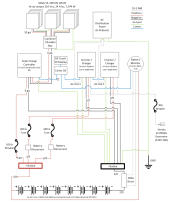
Here is an updated diagram. To keep things neat and tidy, I've decided to use a Midnite Solar Mini DC wiring panel to house most of the connections and breakers, and that is reflected on this diagram. I believe I've also addressed the helpful points of those who responded to the initial diagram.

After research on the grounding and neutral/ground bonding issues (which are not at all well agreed-upon and straightforward in several forums), I now plan to let the N-G relay in the Quattros operate as designed, which means neutral will be bonded to ground while in inverter mode, but not when an external AC feed is in place (e.g. a generator). The main AC distribution panel will not have an N-G bond. Since my generator has a floating neutral, I'll bond N-G using an N-G bonding plug in one of the generator receptacles and tie the generator chassis to my ground rod.

As before, I'd appreciate any feedback on the current version of the diagram.

1646278203909.png
 
i think too much is made of the unheated.... put your batterys and gear in basically a "beer cooler" problem solved... unless your charge controller or inverter work by magic, they generage heat in a small enclosed container.
 
After research on the grounding and neutral/ground bonding issues (which are not at all well agreed-upon and straightforward in several forums), I now plan to let the N-G relay in the Quattros operate as designed, which means neutral will be bonded to ground while in inverter mode, but not when an external AC feed is in place (e.g. a generator). The main AC distribution panel will not have an N-G bond. Since my generator has a floating neutral, I'll bond N-G using an N-G bonding plug in one of the generator receptacles and tie the generator chassis to my ground rod.

As before, I'd appreciate any feedback on the current version of the diagram.
I still don't think grounding the array is a good idea.
Multiple ground rods?

How many structures will this system encompass?
 
I still don't think grounding the array is a good idea.
Multiple ground rods?

How many structures will this system encompass?
Advice I've gotten from the racking dealer has strongly recommended grounding the array. From my reading, grounding the physical structure of the panels and racking is primarily for lightning, which we get a decent amount of. The panel ground is not connected into the electrical wires of the array. I've separated that ground rod from the system grounding, which will handle equipment case and electrical grounds. If there's a lightning event on the panels, the design is that the frame and racking ground will route the surge to ground without impacting the electrical side of things. Also, from what I've read, multiple ground rods is not uncommon, especially in dry areas. Normally you would bond the multiple rods together to provide greater soil contact. In my case, since the rods have two different purposes, I plan to leave them separate.

This system is all self-contained on a metal skinned, wood-frame barn.
 
The inverters seems to have N-G connection in inverter mode. Only one of them should have that connection.
As long as the generator is un-bonded then the inverters can be un-bonded and the only bond should be at the main panel.
The primary reason that inverter/chargers have a bonding relay is so that they can be temporarily connected to a pedestal where the bond will be upsteam and out of one's control when you are attached but within the inverter when you not connected.
 
Back
Top