diy solar

diy solar

Please check my design: 24V 300A

balachai

New Member
Joined
Mar 13, 2021
Messages
67
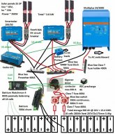
Please see the diagram below - hopefully it's visible to everyone.
24V battery is dictated by existing DC loads, and 100V solar by local regs.
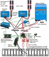
24V system 1d.jpg

Two batteries in parallel, but either one could run alone. The Batrium BMS apparently can be told whether it's working with 13.4 kWh or half that amount, so it can properly monitor state-of-charge for the entire storage.

I'm aware that if one battery was disconnected and then reconnected later when they're at different states of charge, this could lead to a very high surge current between the batteries. Any ideas how to improve this?

For details on wiring the contactor pre-charge etc, I'm planning to copy Jan Gils' system - that diagram is more detailed in this area.
 
Last edited:
Can the canbus protocol disconnect the solar charge controllers?
Maybe even the inverter charger?
 
I don't think you need a class t fuse between the inverter and the busbar.
You could use a something like this
Yeah good point, thanks.

Can the canbus protocol disconnect the solar charge controllers?
Maybe even the inverter charger?
Yep that's what Victron and the_colorist says. And when the BMS reports that the battery's full*, the Cerbo will apparently reduce charging across all sources to the level required to supply loads without charging the battery.

*Edit: or can't charge because it's too cold.
 
Last edited:
I probably need to add another 400A Class T fuse before the contactor. In the event of a fault, it's possible that cable could experience 800A of current, 400A from each battery.
 
Last edited:
Yeah good point, thanks.


Yep that's what Victron and the_colorist says. And when the BMS reports that the battery's full, the Cerbo will apparently reduce charging across all sources to the level required to supply loads without charging the battery.
Cool I wonder if it can also control the battery protect making the contactor redundant.
Just to be clear I'm not suggesting getting rid of the contact.
 
The Battery Protect is just for DC loads. From what I've read it has its own sensor lead to the negative bus. All it has to do is disconnect when the voltage falls below a threshold. I guess the BMS would give it a more accurate reading of battery voltage, but I guess it wouldn't matter. I'm planning to disconnect AC loads at a higher voltage than DC loads, because the DC ones are more important (e.g. fridge).

Ideally the contactor won't ever need to open - it's just the last line of defense in case a cell goes badly out of balance or gets too hot etc.
 
The general recommendation is to have a circuit breaker between the MPPT and the common bus bar.

Check what gauge of wire your 30 amp circuit breakers will allow. If you're using 10 gauge PV wire and combining the two parallel strings at the circuit breaker, then the combined size is 7 gauge. This should work. I used 6 gauge cable on the output side of my circuit breaker in that position and it fit OK.

Make sure your common bus bars can handle the amps you expect the inverter to draw. My bus bars are good for my current install, but if I put in a larger inverter I'll have to replace the bus bars.
 
The general recommendation is to have a circuit breaker between the MPPT and the common bus bar.
Good point - perhaps a fuse would be OK?
Check what gauge of wire your 30 amp circuit breakers will allow.
Yeah I'll look into that, thanks,
Make sure your common bus bars can handle the amps you expect the inverter to draw.
Done on the updated diagram below!
 
It looks like those options might not handle the inverter current, so I've stuck with a class T fuse holder.

Using a Class T fuse in that location isn't wrong. But it is expensive.

Regarding the overcurrent protection between the MPPT and the common bus bar, should you need to turn off power to the MPPT, a circuit breaker is much easier to work with.
 
I probably need to add another 400A Class T fuse before the contactor. In the event of a fault, it's possible that cable could experience 800A of current, 400A from each battery.
800 amps is nuts.
Suggest you use 4/0 with the busbar I linked and a 400 amp zcase fuse.
 
Last edited:
Oh I agree - that would just be in a fault which is why I'd put a fuse to prevent it.

The fault current for inverter circuit is 400 amps.
A 400 amp zcase fuse is fine for that.
Its the battery circuits that need the class t fuses cause that is where the mondo current comes from.
You have some pure dc loads which I will guess are trivial and the big inverter/charger.
5000 ac watts * 1.5 low frequency fudge factor / 24 volts low cutoff = 312.5 dc amps
312.5 dc amps / .8 fuse headroom = 390 fuse amps.
 
Regarding the overcurrent protection between the MPPT and the common bus bar, should you need to turn off power to the MPPT, a circuit breaker is much easier to work with.
True! I'll look into it.
 
Joey, are you saying I don't need a fuse before the Gigavac?
Nope.
I am saying...
You need a class t fuse for each battery as close to the positive terminal as possible.
The wire between the gigavac and the busbar is the same awg as the wires from the batteries.
It terminates on a 400 amp zcase fuse at the busbar.
The inverter/charger wire is the same awg as also gets a 400 amp zcase fuse.
 
Back
Top