You are using an out of date browser. It may not display this or other websites correctly.
You should upgrade or use an alternative browser.
You should upgrade or use an alternative browser.
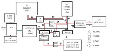
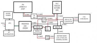
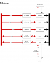
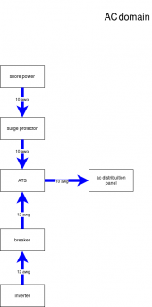
Please check my design.
- Thread starter Brewman
- Start date
Brewman
Solar Enthusiast
- Joined
- May 16, 2020
- Messages
- 511
You have shore power but no ac charger
I will be adding it soon, right now I just want to make sure the wire gauge is correct.
John Frum
Tell me your problems
- Joined
- Nov 30, 2019
- Messages
- 15,233
The symbol abstraction is a pain for me.I will be adding it soon, right now I just want to make sure the wire gauge is correct.
I have to look at the wire and then refer to the legend.
Just saying.
I would use the 125 amp battery fuse as the disconnect unless you have a reason to disconnect frequently. Can add the switch later if removing the fuse becomes a PITN. I prefer to not add additional connections and resistance in the inverter power loop.
The 50 amp breaker to the controller is a bit redundant since the wire is the same as the main battery cable fused at 125. Or could use smaller wire assuming the distance is short from controller to bus.
I don't think the circuit breaker is needed between the solar and controller. Usually not needed unless 3 strings or higher voltage. Does make a convenient switch. 60 volts is getting up high enough you may not want to just remove a wire for service.
I am not sure what that battery connection is off the transfer switch.
Wire seems light to the 12v fuse block. How many amps does the 24-12 converter supply?
svetz
Works in theory! Practice? That's something else
Insufficient information... for example if the panels are 1V @ 250 amps a 40 amp breaker won't cut it ;-)I have labeled all the wire sizes. Please look it over and see if I have it all correct.
But let's assume 30V and 8.2 amps with a local minimum temperature of -25°C and an Isc Temperature Coefficient of 0.04 %/°C. Then with 2P that's 16.4 amps at +25°C, and 16.8 amps at -25°C ( peer approved example math, don't trust any calculations I do ;-). If the code says you have to upsize by 25% that's an ampacity of 21 amps.
Not all copper wire is equal in terms of ampacity. If it's a ground mount and you're using 60°C copper wire (e.g., UF-B) then you'd want gauge 10. But, if you're using 90°C Copper (e.g., THWN-2) then 14 gauge might do. Is it on a hot roof? In a conduit? Hot wires have more resistance and you might have to compensate with a lower gauge.
That's why we have the write-up: What wire gauge should I use? (video). The video is really really good, I definitely recommend it.
Amen! ;-)The symbol abstraction is a pain for me.
Last edited:
svetz
Works in theory! Practice? That's something else
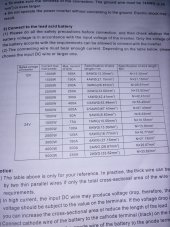
The inverter is 2000W @ 24V, so a normal draw of up to 84 amps. But if it surges to 3000W for 5s that would be 125 amps and 5 seconds might put some serious heat on the wire. I'd look up the manufacturer's recommendations. Also, wire quality makes a big difference, in looking at 3 categories of wire AWG 4 might handle 70 amps, 85 amps, or 95 amps.
Brewman
Solar Enthusiast
- Joined
- May 16, 2020
- Messages
- 511
Brewman
Solar Enthusiast
- Joined
- May 16, 2020
- Messages
- 511
What would be a better way to lable it?The symbol abstraction is a pain for me.
I have to look at the wire and then refer to the legend.
Just saying.
John Frum
Tell me your problems
- Joined
- Nov 30, 2019
- Messages
- 15,233
Just replace the symbols with the nnn awg where nnn is the guage.What would be a better way to lable it?
Brewman
Solar Enthusiast
- Joined
- May 16, 2020
- Messages
- 511
It monitors battery voltage and switches at user designated set points.I am not sure what that battery connection is off the transfer switch.
Stepandwolf
Solar Enthusiast
- Joined
- Nov 14, 2020
- Messages
- 668
Two comments. I am doing a similar build but went with a Victron 3000va. It includes the charger and ATS function. What I am wondering about, I think in my case the shore power goes to the inverter and then to the AC distribution. On your diagram, I don't see a path from the inverter to AC distribution.
Someone asked about the DC>DC converter wire gauge. I planned for the wire to be 8ga, but the wire coming from the converter is only 12ga and it is rated at 40a. How can the converter rated for 40A out use 12ga wires?
Someone asked about the DC>DC converter wire gauge. I planned for the wire to be 8ga, but the wire coming from the converter is only 12ga and it is rated at 40a. How can the converter rated for 40A out use 12ga wires?
I think you’re good to go brewman as long as the fuse block connected to that converter pulls less than 50 amps at 12v which is roughly 25amps @ 24v that fuse of yours shouldn't pop. Oh, also as long as your converter can handle an output of up to 12v at 50 amps and just in case you do pull 50 amps at 12vdc I hope it does pop because 12 wag will not handle 50 amps at 12vdc (I checked on that ampacity link posted above by svetz
Yeah 40a and 12ga doesn’t sound like a good idea. I’d go 30a max and that’s with a good thhn wire.Two comments. I am doing a similar build but went with a Victron 3000va. It includes the charger and ATS function. What I am wondering about, I think in my case the shore power goes to the inverter and then to the AC distribution. On your diagram, I don't see a path from the inverter to AC distribution.
Someone asked about the DC>DC converter wire gauge. I planned for the wire to be 8ga, but the wire coming from the converter is only 12ga and it is rated at 40a. How can the converter rated for 40A out use 12ga wires?
John Frum
Tell me your problems
- Joined
- Nov 30, 2019
- Messages
- 15,233
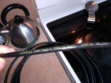
Since you are using thhn...
I suggest you get 4 awg, 6 awg and 12 awg.
4 awg is easy to work with and big enough for the critical path.
6 awg is even easier work with.
12 awg is trivial.
The nice thing about thhn is its relatively cheap.
I prefer to get white, then use red, black and green electrical tape to identify the wires.
Similar threads
- Replies
- 0
- Views
- 196
- Replies
- 25
- Views
- 1K
- Replies
- 23
- Views
- 850


