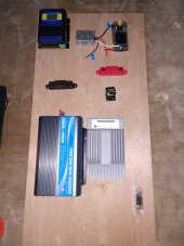
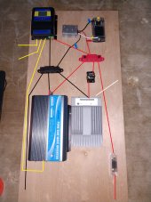
My system is similar, I used 150 amp dc breaker off the battery and use it as a disconnect switch also. 4awg is a bit small for battery to inverter, I tried the original 4awg wires that came with the inverter, they were about 18" long attached to BB that was fed with 2/0 cable. The 4awg got pretty warm after about a half hour running 1600 watt load so I swapped the 4awg to 2/0
You are using an out of date browser. It may not display this or other websites correctly.
You should upgrade or use an alternative browser.
You should upgrade or use an alternative browser.
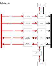
Please check my design.
- Thread starter Brewman
- Start date
Good question on the converter ,mine is the 30 amp model and it just seems to work, worst I did was run a 150 watt water heating element for 5 hours and other than the converter housing getting warm the wires were fine but the 12ga wires are only about 6" longSomeone asked about the DC>DC converter wire gauge. I planned for the wire to be 8ga, but the wire coming from the converter is only 12ga and it is rated at 40a. How can the converter rated for 40A out use 12ga wires
svetz
Works in theory! Practice? That's something else
Temperature correction factor? Probably moot (~1.5%?) since you're a Florida boy ;-)<Given THHN/THWN-2 wire, are the gauges correct given:>
- Panels 2S2P
- VOC: 37.6 V
- VMP: 30.3 V
- ISC: 8.85 A
- Max power current: 8.27 A
- Power Tolerance 0/+3%
- Maximum system voltage: 600V (UL)
How many amps are on each wire? A visual update would be nice.
For general 90°C Copper THHN:
AWG 4 - 95 amps
AWG 8 - 55 amps
AWG 10 - 40 amps
AWG 12 - 30 amps
- The 125 amp fuse for 4 AWG seems high, typically use see a lower slow-blow fuse... but probably depends on the inverter. The snapshot of the page in #9 shows 100 amps and AWG 6. But, you need to add in the amps for the converter, so it can't be determined yet.
- The SCC tracer is 40 amps, but the wire shown is rated for 95 amps and the circuit breaker is 50 amps
- Only 18 amps (2p x ~9) from the panels, so AWG 8 isn't needed
- Can't tell about the gauge of the DC fuse block or converter as you need to know the maximum draw
Last edited:
Brewman
Solar Enthusiast
- Joined
- May 16, 2020
- Messages
- 511
The only thing coming off the fuse box will be LED lights and a few USB chargers. Total load should be no where close to its rated 40A.I think you’re good to go brewman as long as the fuse block connected to that converter pulls less than 50 amps at 12v which is roughly 25amps @ 24v that fuse of yours shouldn't pop. Oh, also as long as your converter can handle an output of up to 12v at 50 amps and just in case you do pull 50 amps at 12vdc I hope it does pop because 12 wag will not handle 50 amps at 12vdc (I checked on that ampacity link posted above by svetz
Brewman
Solar Enthusiast
- Joined
- May 16, 2020
- Messages
- 511
Is over sizing the wire an issue? I was doing this if future expansion happens. The converter is the one off Wills page, and I just noticed I got the gauge backwards, its 12 AWG is in and 10 AWG out. Ill update my drawing soon. @smoothJoey I update your drawings and use to show correction.
Brewman
Solar Enthusiast
- Joined
- May 16, 2020
- Messages
- 511
The nice thing about thhn is its relatively cheap.
I prefer to get white, then use red, black and green electrical tape to identify the wires.
I was able to get the black 4 AWG for free, Id rather have black and red but Ill just band it with colored heat shrink.
John Frum
Tell me your problems
- Joined
- Nov 30, 2019
- Messages
- 15,233
As you wish.I was able to get the black 4 AWG for free, Id rather have black and red but Ill just band it with colored heat shrink.
John Frum
Tell me your problems
- Joined
- Nov 30, 2019
- Messages
- 15,233
THHN is rated for 105C when used in for appliance wiring.Temperature correction factor? Probably moot (~1.5%?) since you're a Florida boy ;-)
How many amps are on each wire? A visual update would be nice.
For general 90°C Copper THHN:
AWG 4 - 95 ampsAWG 8 - 55 ampsAWG 10 - 40 ampsAWG 12 - 30 ampsHope that's of some help!
- The 125 amp fuse for 4 AWG seems high, typically use see a lower slow-blow fuse... but probably depends on the inverter. The snapshot of the page in #9 shows 100 amps and AWG 6. But, you need to add in the amps for the converter, so it can't be determined yet.
- The SCC tracer is 40 amps, but the wire shown is rated for 95 amps and the circuit breaker is 50 amps
- Only 18 amps (2p x ~9) from the panels, so AWG 8 isn't needed
- Can't tell about the gauge of the DC fuse block or converter as you need to know the maximum draw
And 4 awg pure copper with 105C insulation is good for 160 amps.
Interactive Wire Size Calculator
Battery Chargers, Inverters, Solar Components, and Wiring Supplies for Boats, RVs, and Off-Grid Applications.
However, larger is better.
svetz
Works in theory! Practice? That's something else
Exactly! It depends on what you get, for example, the bottom one is for a marine grade wire... and why you need to check the manufacturer's specs rather than any old well-meaning chart on the internet.THHN is rated for 105C when used in for appliance wiring.
And 4 awg pure copper with 105C insulation is good for 160 amps.
Interactive Wire Size Calculator
Battery Chargers, Inverters, Solar Components, and Wiring Supplies for Boats, RVs, and Off-Grid Applications.baymarinesupply.com
Use the charts for what you'll buy. For example, here's the southwire spec (available from homedepot)
Last edited:
John Frum
Tell me your problems
- Joined
- Nov 30, 2019
- Messages
- 15,233
Copper is copper and the insulation temperature rating is its temperature rating.That's marine wire... and why you need to check the manufacturer's specs rather than any old well-meaning chart on the internt.
svetz
Works in theory! Practice? That's something else
Except when it's not, e.g., oxygen-free copper.Copper is copper ...
Should have also said, don't trust the specs unless it's rated by an independent trustworthy source such as UL/ETL/CE.... check the manufacturer's specs ...
Brewman
Solar Enthusiast
- Joined
- May 16, 2020
- Messages
- 511
I'm using a 10 Ton hydraulic crimper it that helps with your question.Assuming you are using compression lugs my concern is how well will they cold weld to thhn.
Thhn is thick strand, from memory there are only 19 strands in bog standard 4 awg thhn.
Oversizing is usually only an issue for your walletIs over sizing the wire an issue? I was doing this if future expansion happens. The converter is the one off Wills page, and I just noticed I got the gauge backwards, its 12 AWG is in and 10 AWG out. Ill update my drawing soon. @smoothJoey I update your drawings and use to show correction.
Brewman
Solar Enthusiast
- Joined
- May 16, 2020
- Messages
- 511
When it comes to the main fuse, it has to be able to handle the inverter and buck converter. As per the manual for the inverter it says 100A, the converter is 12V 40A out so that becomes 24V 20A in. Total is 120A, Should I up my main fuse to 150A or is 125A fine.
As for the PV circuit breakers, I should lower them from 40A to something like 20A. If the array is not big enough for really needing the breakers can I just leave the 40's as disconnects and if the array gets larger then resize them if needed?
As for the PV circuit breakers, I should lower them from 40A to something like 20A. If the array is not big enough for really needing the breakers can I just leave the 40's as disconnects and if the array gets larger then resize them if needed?
John Frum
Tell me your problems
- Joined
- Nov 30, 2019
- Messages
- 15,233
2000 ac watts / .85 conversion efficiency / 24 volts low cutoff + 20 dc amps / .8 fuse headroom = 147.549019608 fuse amps
That is pushing it for 4 awg wire.
It may be rated for 105C but I really doubt you want to get anywhere near that.
That is pushing it for 4 awg wire.
It may be rated for 105C but I really doubt you want to get anywhere near that.
Similar threads
- Replies
- 0
- Views
- 157
- Replies
- 25
- Views
- 1K
- Replies
- 23
- Views
- 810
- Replies
- 21
- Views
- 850


