diy solar

diy solar

Please check my in process work

RoadTurtle

Solar Enthusiast
Joined
Mar 30, 2022
Messages
365
I'm nearing completion for the 12V system. !20V will take a bit longer. Hoping to {shudder} put a hole in the roof tomorrow, but think I have a plan for that. I bought 100' of red and black cable, but 25' may have been enough :) Wire is pulled 1/2 way up the wall. Not totally happy with how things are coming together on the roof, but it is what it is.

Anyway, I need to bring down the solar wires, move two 100ah batteries from battery box to front compartment, clean things up a bit and connect the 12v wires to the trailer's "buss bar". Figuring to start the system while I work on the 120v runs.

Looking for good and bad comments on what I have done so far. I ordered the last wire from the fuse to the buss bar tonigh, also the networking cables. 712 will go in upper right corner, Cerbo display in the 5th wheel. Two completely independent strings of 600w. One string could go to 800w, the other string, but more challenging to increase. 400ah total battery, with room for 600ah. All 12v. Buss bars have a cover.
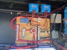
12V 2022_02_01.jpeg
 
non polarized breaker to shut off inbound solar energy.

There's a resetting breaker on the other side of the wall for the trailer supply where the current batteries are located. This was the factory configuration
 
The disconnect between the PV and the solar charge controller should be a dual pole breaker with positive and negative going through the breaker. There's a thread here that explains why. The gist of it is that positive and negative need to be cut off at the same time. I don't see a negative cable going into the solar charge controllers. That is not how I did mine, nor have I seen it done that way. I have the same pair of solar charge controllers and each solar charge controller has it's own breaker.

There should be a circuit breaker on BOTH sides of the solar charge controller. When you need to work on the PV side you're going to want to cut battery power to the solar charge controller, as well as cutting PV power to the solar charge controller.

Strain relief. You're going to break things the way you have the cables configured. At the very least, the connections could come loose from vibration.

I ran cables from each battery to common connection point. In your case, both batteries would each have a negative cable going to the shunt and a positive cable going to the Class T fuse.

I don't see a fuse/breaker on the cables going to the Multiplus.
 
Last edited:
Thank you for the detailed reply

The disconnect between the PV and the solar charge controller should be a dual pole breaker with positive and negative going through the breaker. There's a thread here that explains why. The gist of it is that positive and negative need to be cut off at the same time. I don't see a negative cable going into the solar charge controllers. That is not how I did mine, nor have I seen it done that way. I have the same pair of solar charge controllers and each solar charge controller has it's own breaker.
Why do I need to break both positive and negative.? Fuses and 120v CB only break the positive. Cables coming down from the roof are in process, that why you don't see pos or neg solar wires right now.

There should be a circuit breaker on BOTH sides of the solar charge controller. When you need to work on the PV side you're going to want to cut battery power to the solar charge controller, as well as cutting PV power to the solar charge controller.
Big shut off switch will shut off battery power to SCC. I did struggle with not using a fuse from SCC to buss bar, and will take a look at that again. 50a max output, and wires capable of 60a, is a fuse/CB really required?


Strain relief. You're going to break things the way you have the cables configured. At the very least, the connections could come loose from vibration.
What do you suggest for strain relief? I will be retaining the wires at the top of the board, just haven't gotten to it yet. I could attach the wires the backer board.

I ran cables from each battery to common connection point. In your case, both batteries would each have a negative cable going to the shunt and a positive cable going to the Class T fuse.
4 batteries will be paralleled, and pos goes directly to the fuse after the shut off switch.

I don't see a fuse/breaker on the cables going to the Multiplus.
Is this because I'm running two cables instead of one 4/0?
 
Why do I need to break both positive and negative.? Fuses and 120v CB only break the positive. Cables coming down from the roof are in process, that why you don't see pos or neg solar wires right now.

Why to use a dual pole breaker on the PV circuit.


Big shut off switch will shut off battery power to SCC. I did struggle with not using a fuse from SCC to buss bar, and will take a look at that again. 50a max output, and wires capable of 60a, is a fuse/CB really required?

There may be times when the rest of the system is to stay energized but you want to work only on the PV or MPPT branch.

Over current protection is there for safety. It is common practice to use over current protection on every wire.

What do you suggest for strain relief? I will be retaining the wires at the top of the board, just haven't gotten to it yet. I could attach the wires the backer board.

Every wire that can move should be secured. Even the little power wires going to the Cerbo GX and the shunt. I found that the inputs on the top of the Cerbo GX (the side opposite of where the power cable goes in) weren't very solid. The connectors just didn't feel secure. They could easily come out on my device. So I secured every cable going in.

The 2/0 cable between your shunt and the negative common bus bar is secure and does not need any strain relief. If your backer board was about 10" wider you could more easily secure the wires, especially the three cables going into the left side of your positive bus bar.

4 batteries will be paralleled, and pos goes directly to the fuse after the shut off switch.

Paralleling batteries using traditional lead acid battery wiring techniques is suboptimal. If it isn't done right you'll end up with unbalanced batteries within the battery bank. See this excellent thread that uses math to explain the problem and shows how to resolve it.


Also see this Victron Wiring Unlimited white paper that is located in the Resources section of the forum:


Is this because I'm running two cables instead of one 4/0?

It doesn't matter if you run one cable or two. There should be a fuse there. I'm running the same cable configuration. Two 2/0 cables from the bus bar to the Multiplus. Each cable has a 200 amp fuse on it, right at the bus bar.
 
Why to use a dual pole breaker on the PV circuit.

It's not being used as an over current protection, but instead a switch. Panels are individually fused, and I'm way over wired given the panels output.

There may be times when the rest of the system is to stay energized but you want to work only on the PV or MPPT branch.
understand

Over current protection is there for safety. It is common practice to use over current protection on every wire

Every wire that can move should be secured. Even the little power wires going to the Cerbo GX and the shunt. I found that the inputs on the top of the Cerbo GX (the side opposite of where the power cable goes in) weren't very solid. The connectors just didn't feel secure. They could easily come out on my device. So I secured every cable going info
The 2/0 cable between your shunt and the negative common bus bar is secure and does not need any strain relief. If your backer board was about 10" wider you could more easily secure the wires, especially the three cables going into the left side of your positive bus bar.
That's a 4/0 cable and it's not going to move. The project board would have been nicer if it was bigger, but it's not.
Paralleling batteries using traditional lead acid battery wiring techniques is suboptimal. If it isn't done right you'll end up with unbalanced batteries within the battery bank. See this excellent thread that uses math to explain the problem and shows how to resolve it.


Also see this Victron Wiring Unlimited white paper that is located in the Resources section of the forum:

It doesn't matter if you run one cable or two. There should be a fuse there. I'm running the same cable configuration. Two 2/0 cables from the bus bar to the Multiplus. Each cable has a 200 amp fuse on it, right at the bus bar.
I've seen a lot on the diagonal connection, and theory is great, but the reality of my current experience with two batteries, the voltage is exactly the same in both batteries, which also corresponds to what will found in his battery bank, IRC 5 batteries. I made sure the battery cables are all the same length, guess the proof will be in the results.
 
Two batteries are fairly easy. More than two and it gets interesting. If each battery is independently wired then you'll be OK. If you have cables going between each battery, that's when it gets to be a problem.
 
Two batteries are fairly easy. More than two and it gets interesting. If each battery is independently wired then you'll be OK. If you have cables going between each battery, that's when it gets to be a problem.
so what do you do, wire to a buss bar and then wire to another buss bar?
 
so what do you do, wire to a buss bar and then wire to another buss bar?

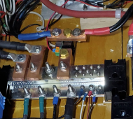
Something like that. You have open spots on your bus bar. Double up a couple of the minor circuits on one stud, then you have room for the batteries. Or, do something like what I did in the picture below. The copper bus bar in the center top of the picture is the negative cables from the two batteries going into the shunt. In your case, you could put all four battery cables on the same bus bar that I have in the picture. One battery on top, the other on the bottom, same thing on the other side.

1675400332607.png
 
Back
Top