diy solar

diy solar

Please critique my off grid system design

offgridpower

Off Grid Simple Living AZ
Joined
Nov 19, 2020
Messages
22
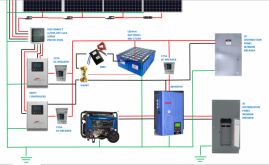
I would appreciate your critique of my off-grid solar design pictured below. The system will generate 6400W, with 13.8 kWh LifePo4 storage and a 6000W split phase inverter. It will be a split system with separate 110/220VAC and 48VDC distribution panels and backup generator.


I would especially appreciate your input on: fuse and breaker size and location, grounding, and general wiring. As well as anything else that you may see that is not optimal.
Solar System Sketch Rev1.png
 

Attachments

  • Solar System Sketch Rev1.pdf
    533.6 KB · Views: 7
Welcome to the forum.

What part of AZ?

Most parallel bridge connectors are only rated for 30A, so the ones closest to the charge controller may be over-spec.

What is between the panels and the MPPT?

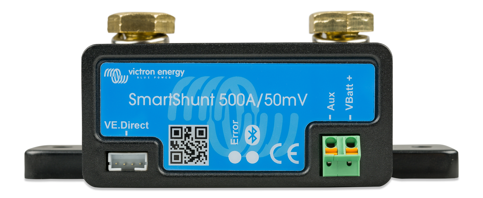
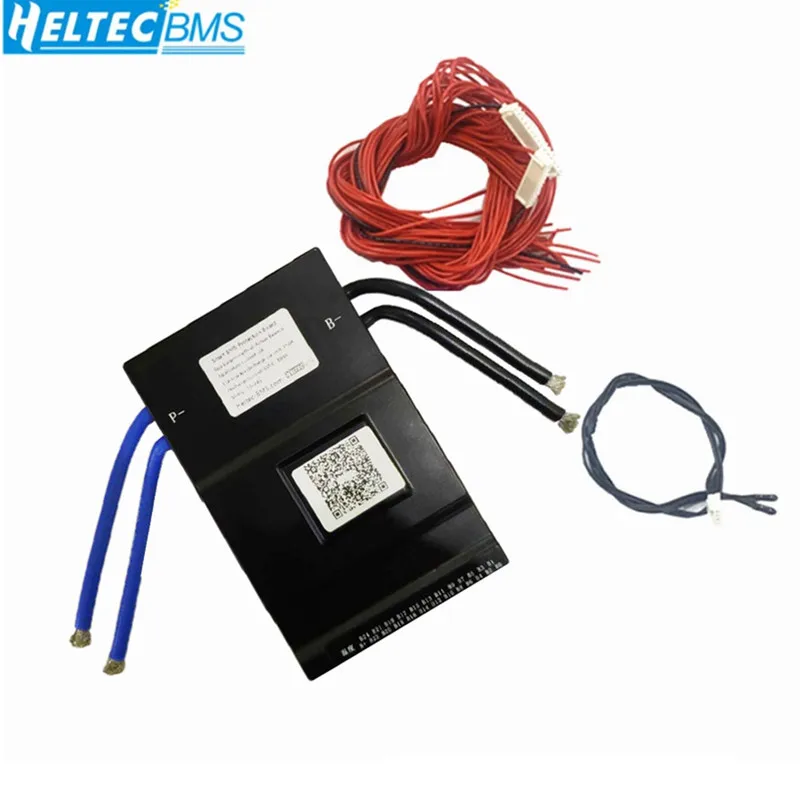
Your BMS needs to be the only thing connected to the (-) of the battery terminal. A shunt for a battery monitor gets connected to the BMS output and everything (-) gets connected to the shunt. Your inverter bypasses the BMS. Make sure your BMS supports both the charge and discharge currents needed. The cells are likely limited to 136A and 272A, respectively.

You need independent breakers on each (+) line exiting the MPPTs, each 1.25X the max current.

150A * 48V = 7200W. Will you ever have a surge that might last several seconds? Size for current * 1.25.

For that kind of size and panel power, your battery seems pretty anemic. I would expect about 2X that unless you've deliberately oversized your panels.

Size your generator appropriately. You want to run a generator around 70% rated continuous for fuel efficiency. Operating a big generator at low power can easily burn 30% more fuel per kWh.

I am not qualified to comment on the grounding.
 
Hi snoobler, thanks for your well thought out reply!! I will try to respond to your points and answer your questions. I have a lot to learn, so please forgive my ignorance.
  • We are in Cochise County!
  • I will look into a higher rated bridge connector.
  • What is between the panels and the MPPT? I am considering a prefabricated box between the panels and the MPPT that includes: surge arrestor(for lightning strikes), a 50A breaker, and quick disconnect. All separate for each array, all in the same box.
  • Your BMS needs to be the only thing connected to the (-) of the battery terminal. A shunt for a battery monitor gets connected to the BMS output and everything (-) gets connected to the shunt. So, I need to add a shunt between the (-) battery terminal and the BMS and then attach the (-) from the Inverter and DC distribution panel to that? Are there any specs on the shunt that I need to know?
  • Your inverter bypasses the BMS. What do you mean by this? Should I route the back feed charge lines from the inverter back to before the BMS? Or are you referring to where the (-) line is coming from?
  • As far as the breaker on the (+) lines leaving the MPPS, I was planning to connect the (+) lines from both controllers prior to entering the breaker box and use a breaker that is rated for the MPPT (they are both rated the same). Would that be a problem? I could run them through separate breakers and join them after: would that be better? Why?
  • The MPPTs are rated for a max battery output of 100A. So, would I use a 125A breaker between the MPPT and batteries?
 
Hi snoobler, thanks for your well thought out reply!! I will try to respond to your points and answer your questions. I have a lot to learn, so please forgive my ignorance.
  • We are in Cochise County!

Cool. Our place is in Apache.

  • I will look into a higher rated bridge connector.
  • What is between the panels and the MPPT? I am considering a prefabricated box between the panels and the MPPT that includes: surge arrestor(for lightning strikes), a 50A breaker, and quick disconnect. All separate for each array, all in the same box.

Ah. I should probably look into that myself. :)

  • Your BMS needs to be the only thing connected to the (-) of the battery terminal. A shunt for a battery monitor gets connected to the BMS output and everything (-) gets connected to the shunt. So, I need to add a shunt between the (-) battery terminal and the BMS and then attach the (-) from the Inverter and DC distribution panel to that? Are there any specs on the shunt that I need to know?

No.

Battery (-) ------ BMS ----- Shunt ----- [all loads and chargers]

The shunt is for a battery monitor is to compute the actual % SoC of the battery as nothing else in the system can. Will lists a few on his site:


The Victron units are GREAT, but the "budget" one with the 350A shunt should be fine.

  • Your inverter bypasses the BMS. What do you mean by this? Should I route the back feed charge lines from the inverter back to before the BMS? Or are you referring to where the (-) line is coming from?

You attached the inverter (-) directly to the battery. Hopefully the text sketch above clarifies.

  • As far as the breaker on the (+) lines leaving the MPPS, I was planning to connect the (+) lines from both controllers prior to entering the breaker box and use a breaker that is rated for the MPPT (they are both rated the same). Would that be a problem? I could run them through separate breakers and join them after: would that be better? Why?

Each conductor needs over current protection. That's code. They're also useful if you want to easily isolate one or the other SCC.

  • The MPPTs are rated for a max battery output of 100A. So, would I use a 125A breaker between the MPPT and batteries?

That should be fine. Just make sure the wire can handle the 100A or more.

Another thing - you can't charge LFP below freezing. May not be a big concern for you depending on your elevation (we're at 6800', so it's an issue). If it's a possibility, you need low temperature charging protection.
 
Cool. Our place is in Apache.


Ah. I should probably look into that myself. :)


No.

Battery (-) ------ BMS ----- Shunt ----- [all loads and chargers]

The shunt is for a battery monitor is to compute the actual % SoC of the battery as nothing else in the system can. Will lists a few on his site:


The Victron units are GREAT, but the "budget" one with the 350A shunt should be fine.


You attached the inverter (-) directly to the battery. Hopefully the text sketch above clarifies.


Each conductor needs over current protection. That's code. They're also useful if you want to easily isolate one or the other SCC.


That should be fine. Just make sure the wire can handle the 100A or more.

Another thing - you can't charge LFP below freezing. May not be a big concern for you depending on your elevation (we're at 6800', so it's an issue). If it's a possibility, you need low temperature charging protection.
Thank you very much!! You have given me a lot to think about. I will make the changes on my schemantic and update the post.
 
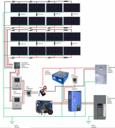
Ok, I have revised the schematic based on the advise I have revcieved. Please take alook and let me know how this looks!! I added a shunt and a breaker and redirected my (-) wiring. I also changed my breaker amerage.
Revised Off Grid System.png
 
Cool. Our place is in Apache.


Ah. I should probably look into that myself. :)


No.

Battery (-) ------ BMS ----- Shunt ----- [all loads and chargers]

The shunt is for a battery monitor is to compute the actual % SoC of the battery as nothing else in the system can. Will lists a few on his site:


The Victron units are GREAT, but the "budget" one with the 350A shunt should be fine.


You attached the inverter (-) directly to the battery. Hopefully the text sketch above clarifies.


Each conductor needs over current protection. That's code. They're also useful if you want to easily isolate one or the other SCC.


That should be fine. Just make sure the wire can handle the 100A or more.

Another thing - you can't charge LFP below freezing. May not be a big concern for you depending on your elevation (we're at 6800', so it's an issue). If it's a possibility, you need low temperature charging protection.
snoobler, I posted an updated schematic below, could you take a look at it and let me know if i corrected the issues that you identified? Thanks in advance, I really appriciate your input!
 
I think you have it. Again, confirm your grounding scheme is appropriate with another resource. I'm bad at it.
 
actually, I'm pretty sure you will have a Ground from the Inverter AC out to the AC panel too. Since it's a split phase 120/240V inverter, you'll have L1, L2, N and G to the AC panel.

You show two earths, if you have two earths, they should be bonded. Better to have just one if you can manage it.
 
Back
Top