diy solar

diy solar

Please help me buy PV wires/cables! :) And setup array. AC-300

Paradise

New Member
Joined
Oct 4, 2021
Messages
15
Hi! I need yall's help again.... So. . . .

I bought solar panels. Six 440 Watt panels
I bought the AC-300 solar generator w 4 batteries
I bought to help with the solar charging: PV Voltage Step Down Module (D300S)


Last step, I need to buy cables.

I figure my solar panels will be about 100-125 feet from my AC-300. I would like to buy the cables that already have the MC4 connections attached.
Would 10 AWG be okay? Also, what configuration would be best to set this up? (3 series, 2 parallel? Or 2 series, 3 parallel? Or just 6 straight into the AC-300???)


SPECS
Solar panels:

440 watt each (Bought six of them for a total of 2,640 watts)
VOC = 49.62
VMP = 40.99
IMP = 10.74

AC-300
Solar Input: 2400 watts, (12-150V), 2x12A

PV Voltage Step Down Module (D300S)
Accept 3000W Max Input Power
Step down the voltage of rigid panels to 120V from 550V
Starting voltage = 120V
Max DC input current = 15A


THANK YOU!!!!!!!!! :) :)
 
would like to buy the cables that already have the MC4 connections attached.
Would 10 AWG be okay? Also, what configuration would be best to set this up? (3 series, 2 parallel? Or 2 series, 3 parallel? Or just 6 straight into the AC-300???)


SPECS
Solar panels:

440 watt each (Bought six of them for a total of 2,640 watts)
VOC = 49.62
VMP = 40.99
IMP = 10.74
A lot going on here.
The first thing I noticed is that 10ga PV wires are limited to 30A so 3S probably won’t be ok. The stepdown has a 15A limit? Not sure all this will get along well.

I don’t know that 300 unit so I can’t speak to the rest
 
Making PV Cables is simple, so I recommend getting MC4 Crimpers. I have never been able to accurately measure a long run. What I thought was 30’ one way ended up being 45’

You can only hook 2 panels in series, none in parallel, but there are two inputs so you can use 4 panels total. You can’t hook the panels in parallel because you’re limited to 12 amps and these panels push up to 11 amps. Can;t have 22 amps input according to specs. For limitation of two panels, 150 volts is the max input and at 49.6 volts, when it gets cold, panels push more voltage which would exceed the 150 volt limit. Excess voltage will kill a SCC quicker than excess amperage.

Check the voltage loss calculator here:


I put in 10 AWG, 80 volts (VMP) and 11 Amps (IMP) and got 4.31% loss. Tha exceeds the 3% I’d like to see. You could get an 8 AWG MC4 connector and 8 AWG wire, and that would meet the less than 3%, but those 8 AWG MC4s are rare to find.
 
So, I'm a little more confused now. I guess 8 gauge cables are the way to go. And the DIY with the crimpers.


Is this even possible? (To get in 2,400 watts to the generator/battery). With these panels I bought? I thought with the voltage step down module I should be able to make this work?
 
Is this even possible? (To get in 2,400 watts to the generator/battery). With these panels I bought? I thought with the voltage step down module I should be able to make this work?
I am unfamiliar with a voltage step down module between a panel and an SCC. I also don't know very much about the AC-200 or AC-300. If that's an accessory for it, than maybe it will. In general, the manuals I've read for SCCs say only use solar panels and put nothing between the solar panel and the SCC. Maybe this generator does something different.
 
I am unfamiliar with a voltage step down module between a panel and an SCC. I also don't know very much about the AC-200 or AC-300. If that's an accessory for it, than maybe it will. In general, the manuals I've read for SCCs say only use solar panels and put nothing between the solar panel and the SCC. Maybe this generator does something different.

Thank you! Yes, the step down module was built for this system, as an add-on.

So, 8 gauge wire would be the way to go? Or can I get away with 10 gauge? Assuming like 100 ft between panels and battery.

I tried using the voltage calculator but got too confused. I don't know all the terminology.
 
So, 8 gauge wire would be the way to go? Or can I get away with 10 gauge? Assuming like 100 ft between panels and battery.
I don’t have a good answer.

I’ve started out 10 AWG on each end for about a foot and added 40’ of 6 AWG with a butt splice to stay underneath that 3%, but that may actually be a paper gain because the butt splice has Some loss and voltage drop but impossible for me to measure.

The 8 AWG connectors are probably not MC4, but likely Amphenol H4 connectors. Both are UL rated, but not when you mix them up with an MC4 from the panel and H4 to the SCC.

Other people don’t worry about the loss in a 150‘ run of solar panels. Its not a 1’ way to skinny inverter cable that will heat up dangerously hot. a 4.3% loss means If it takes 4 hours to charge your panels, may take 4 hours and 40 minutes.

Yes, the step down module was built for this system, as an add-on

I don’t understand the step down module very well. If you really can add three panels to this you’d be fine with a 150’ of 10 AWG if these are the numbers:


I really can’t speak to it. I was looking at Bluetti’s a few weeks ago and don’t recall a step down module. I wonder if there’s a cost like less efficiency or maybe an idle draw.
 
I am using an MPP Solar L2424 vs the step down module being they are roughly the same price and more features to charge my AC300 and B300. Then you are limited to the MPP since you just charge the B300 using AC off the MPPT. This way the volt/amp limits of the AC300 is less of an issue… just use the 120 output… and you can add a battery to the setup for even more power storage.

I do need to run 100' to one location and 20' more to another, so will need a 120' cable run to reach the garage from the backyard. Thinking adding extensions for the extra footage would add even more loss. Still debating it…
 
I might add that I bought 4 - 200watt Rich Solar panels for charging the AC300 directly for the trailer and road trips. Once the AC300 arrives, I am curious how long it will take to charge the B300 with the smaller panels. When at home I will use the 120 out of the MPPT to charge it faster than panels. I have 4 365watt panels going to the MPPT for testing and can add more, likely will to maximize charging and power for the garage and likely a rack mount battery.
 
9DBBDBB7-A8F0-4B5F-A21E-18AB4E8A1B8E.pngThe 8 AWG connectors are probably not MC4, but likely Amphenol H4 connectors. Both are UL rated, but not when you mix them up with an MC4 from the panel and H4 to the SCC.
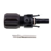
8ga solar cables are available with MC4s.
They claim 55A but I don’t think MC4s are rated for 55A!
IMHO they won’t be usable for over 30A but they can help with voltage drop efficiency- both real, and imagined :)

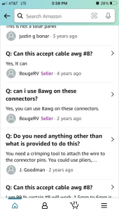
The Amphenol H4 I think is merely their nomenclature for MC4 connectors is it not?
Their information blurb states, “The H4 PV Panel Connector is dual-rated for UL and TÜV. The connector meets NEC 2008/2011 requirements without the need for extra locking collars or locking sleeves and is available in four different gauges including 14 AWG rated at 32A, 12 AWG rated at 40A, 10 AWG rated at 44A and 8 AWG rated at 65A.” and identifies itself for the make part as, “Amphenol H4CMC6DM Cable Connector, H4, Male
Cable Connector, Crimp Type. For use with H4CFC6DM Female Connectors. Includes Metal Pin. 1000V Type: MC Type 4, Connector”

Am I reading that properly or looking at thee wrong part?

These also accept 8ga

I’m intrigued by the 55A number.
Not too sure about that.
 
For my NEC wire ampacity chart, 8aWG at 90 C insulation is good to 55 amps.

There’s different articles out there. For me in my builds, I’ve decided not to mix Amphenol and MC4 connectors despite the fact they click together and you would not tell the difference. I have never used the Amphenol H4 connectors, but I have decided to stop looking. Now if I need to go to 8 AWG, I will put a higher voltage on there. With the latest crate build, I’ve gone with higher voltage with more panes in series to avoid a lower voltage higher amperage equivalent for losses.

This is one of many google results that stated both sides:


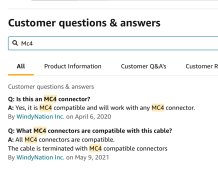
These are MC4 compatible connectors. Not sure how much of a difference it makes. My GUESS is these are Amphenol H4 connectors. Both are UL rated and plug into each other, but would be a code violation used together. From the same link you have.
D52CF3FC-ED0C-4E53-AB7B-41ABDA2D1D43.jpeg
I used to think the MC4 were the answer to water corrosion bcause of the IP rating. Apparently not. Not sure what difference mixing a MC4 and compatible connector would be.

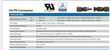
Appears Amphenol may have discontiued the 8 AWG wire size, but here are the ratings for the 14 AWG, 12 AWG, AND 10 AWG ratings:

8C4A7472-B8A5-4A59-902D-69E4327A3291.jpeg
 
Yes, I’m not a fan of mixing brands anymore.
I haven’t had a known bad situation plugging in Bouge product to WindyNation but at this point I’ll never know because I am pretty sure everything is Bouge now. A few weeks back I unscrewed, examined, and reassembled every MC4 with a healthy dose of lexel on the wire sleeve.
I just received an order of 30 pairs of Bouge MC4s because they seem to be working.
 
Back
Top