diy solar

diy solar

Please help me to figure out my DALY bms

kenryan

Solar Enthusiast
Joined
Jun 29, 2021
Messages
190
I received my 300 amp Daly bms yesterday and have a few questions. I know these are dumb questions, but I have never done this before and the "instructions" are so appalling that just don't want to make a stupid mistake.

I am building a 24 volt (8s) battery.

As you can see in the picture, there are two each P- and B- leads. Each one is size 2 AWG.
1. Am I correct in thinking that these are just doubled up for added current carrying capacity and can be treated as single cables?

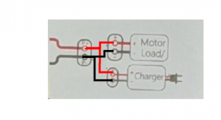
If you follow the P- lead in the picture instructions, you see it goes to an object that looks like it could be a bus bar. But looking closer it does not seem like it is a bus bar. Instead it appears to be two separate terminals, isolated from each other (P+ and P-).

2. Is that object meant to represent two isolated terminals or a bus bar?

To the right of the P+ / P- object are two more objects (Motor/Load and Charger). There is an indication that there is a connection between these objects and the P+ and P- leads, respectively.

3. Am I correct in assuming that the diagram is meant to show that the positive cable on the load side of the system goes to P+ and the positive cable on the charge side of the system goes to P-?

FYI the instructions appear to be for two different styles of BMS -- "regular" and "smart" with the smart version apparently having bluetooth output. I do not have the smart version, but I am supposed to have temperature protection.

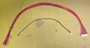
The BMS came with the leads shown in the second picture. I understand that the group of 8 leads are the balance leads and I think I understand how to connect them. But I am unclear as to when it is okay to plug these leads into the BMS.

4. Does it matter when the balance leads are plugged into the BMS?

The other leads in the picture are a set of two wires and a plug on one end. I am 99% certain that these are for temperature sensing (the BMS was advertised as having hot and cold temperature protection). I cannot pull anything out of the instructions with regards to connecting these two wires. I am guessing that maybe one wire goes to the main positive of the battery and the other goes to the main negative of the battery.

5. Is my assumption correct?
6. Are these connections polarity sensitive?
7. For temperature sensing, wouldn't there need to be a temperature probe at the battery? Can a simply wire sense the temperature of the battery? Or is the BMS using ambient temperature of the BMS as the temperature?

Thanks in advance for any help with these extremely basic questions.

8. Any other "gotchas" I should watch out for?

9. Does @Will Prowse have a video that covers this? I'm sure he does, but finding it is another thing. Anyone have a link?

Thanks in advance.
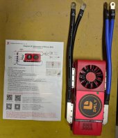

bms.jpgbms-leads.jpg
 
1. Am I correct in thinking that these are just doubled up for added current carrying capacity and can be treated as single cables?
Yes
2. Is that object meant to represent two isolated terminals or a bus bar?
Two Isolated Terminals
3. Am I correct in assuming that the diagram is meant to show that the positive cable on the load side of the system goes to P+ and the positive cable on the charge side of the system goes to P-?
EDIT: The following answer was corrected:
This is what the diagram is trying to say:
1628106985127.png
I do not have the smart version, but I am supposed to have temperature protection.
Things may have changed, but in the past the 'non-smart' Daly BMSs did not have low temp protection. Will had a video a while back that showed a Daily 'dumb' that claimed to have low temp protection actually did not have it.
4. Does it matter when the balance leads are plugged into the BMS?
Yes. Plugging the harness into the BMS should be done AFTER the B- power lead is hooked to the battery. In generall, the ballance harness is the last thing I hook up when I am building up a system and the first thing I unplug if I am going to work on a system.

The other leads in the picture are a set of two wires and a plug on one end. I am 99% certain that these are for temperature sensing (the BMS was advertised as having hot and cold temperature protection). I cannot pull anything out of the instructions with regards to connecting these two wires. I am guessing that maybe one wire goes to the main positive of the battery and the other goes to the main negative of the battery.

5. Is my assumption correct?
6. Are these connections polarity sensitive?
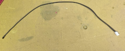
This is a temp sensor/probe:
1628104848945.png
The little 'blob' in the opposite end from the white plug is a PTC resister, probably a 5K PTC resister. (PTC stands for Positive Temperature Coefficient. As the temp goes up the resistance goes up) The little black 'blob' should be taped to the cells someplace and the white plug should be plugged into the BMS (The wires should NOT be wired to the battery +/-). The picture of the instructions is blurry, but it looks like the connector is on the side of the BMS.... However, the picture in the instructions looks a little different than your BMS. In the past, the Dumb daily BMSs did not have something like this.... but like I said, that might have changed. If there is no place on the BMS that the little white plug plugs into then it is not for your BMS and was probably only intended for the 'smart' version of the BMS. ?


For temperature sensing, wouldn't there need to be a temperature probe at the battery? Can a simply wire sense the temperature of the battery? Or is the BMS using ambient temperature of the BMS as the temperature?
All of the BMSs with low temp disconnect that I have worked with have a probe/sensor that gets taped to the battery. It is conceivable for a BMS to use ambient temp..... but it would not work very well. This is particularly true for a high amp BMS like yours. The heat dissipated by the BMS would play havoc with any sensor intended to detect low temp situations.
 
Last edited:
Thank you @FilterGuy! Extremely helpful.

Yes, there is a port for plugging in the temp sensor, so it looks like Daly has truly added low temp protection. If I succeed with my battery build I will test it and post the results here.

The muddled mess of "instructions" from Daly seems to be coming into a little more focus. It seems to me now that in the instructions (see previous pic) the object I am calling P+ / P- is probably meant to represent the positive and negative poles of the completed battery. Is that correct?

If yes, then it seems that my statement #3 above would be incorrect. Right?

I have a new question. I don't want to add an active balancer, but I would like to be able to monitor each cell voltage. Is there a device for doing that, separate from my dumb bms?

Thanks again.
 
3. Am I correct in assuming that the diagram is meant to show that the positive cable on the load side of the system goes to P+ and the positive cable on the charge side of the system goes to P-?
I just reread this and am a bit confused.

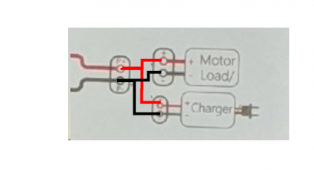
this is what the picture is trying to say
1628106834310.png
 
I have a new question. I don't want to add an active balancer, but I would like to be able to monitor each cell voltage. Is there a device for doing that, separate from my dumb bms?
Will used to use something like that but I have never had/used one so I am not sure where to get them.
 
If I succeed with my battery build I will test it and post the results here.
Yes.... Please do. I am particularly interested to find out how the BMS reacts to low temp.
* Does it do anything?
* Does it shut off just charge?
* Does it shut off Charge and Discharge?

Daly was Will's Go-to BMS back in the day, but he always complained about the lack of low temp protection. Since things like the JBD/Overkill BMS came out, will has not talked much about the Daly line of BMSs.

When Daly first released their Smart BMSs I was excited because they had some high-amp smart BMS. Unfortunately, they had a *lot* of problems with both HW and SW. I purchased one that I never got working. Sadly, they started leveraging their designs to the 'dumb' BMS lines and screwed up their tried-and-true line of BMSs as well. They have been doing rapid fire updates of both the HW and SW so hopefully they have the issues worked out now. If you have a good experience, maybe I will put them back on my list of BMSs to consider.
 
BTW: Even if you have issues with the Daly.... please post it. We can all learn from both successful and problematic builds.
 
Unfortunately, they had a *lot* of problems with both HW and SW. I purchased one that I never got working. Sadly, they started leveraging their designs to the 'dumb' BMS lines and screwed up their tried-and-true line of BMSs as well. They have been doing rapid fire updates of both the HW and SW so hopefully they have the issues worked out now.
What are "HW" and "SW" ?
 
BTW/FYI: One good thing about Daly is that their advertised discharge current is for 'continuous duty'. (but I would never run any BMS at the full rated continuous current). Some BMSs likw the ANT BMSs are advertised at their peak current and you have to look close at what the continuous current rating is.

Along those same lines, the Daly BMSs almost always rate their charge current at 1/2 their discharge current.
 
I am concerned about this statement:
"3. Am I correct in assuming that the diagram is meant to show that the positive cable on the load side of the system goes to P+ and the positive cable on the charge side of the system goes to P-?"

By system, are you referring to the BMS?

I am where the Op is, I am getting ready to wire my Daly 250A. The 250 has single 2ga leads vs a pair or them.

I interpret the diagram differently. The BMS goes from battery negative (B-) to negative bus bar (P-). The only connection to power is the cell connections. Look at the picture this way.

On the far left in a dotted outline is the battery. The B- runs from the BMS to the battery -. On the other end is the battery positive going to the bus. The "motor/load" and charger to the right are just showing them connected to the +/- bus. They are depicting the connection in an artsy manner, not appropriate.
Yup. We sorted that out in post 4:
 
Back
Top