diy solar

diy solar

Please help me with panel placement

I will definitely be exporting to the grid.
And it does seem like I should be able to use my air conditioner most of the time because it runs the most when the solar is producing the most.
I should be able to connect the air conditioner to the smart loads connection of the Sol-Ark which is programmable based on battery state of charge.
But I want to proceed slowly with my batteries. My top priority is to get solar up and running. I would like to have the system battery ready for the permit inspection. But I don't necessarily need to have the batteries hooked up for the inspection. The Sol-Ark is capable of operating without batteries. If I can get the inspection over with without batteries, that would probably be the smoothest way to go as long as I don't need an additional inspection.

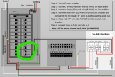
My main breaker is on the bottom so these breakers go on the top. My marking is sloppy. I mean the two 50A that are tied together.
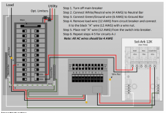
1601745572263.png
 
Last edited:
Something funny in that drawing.
Ganged 50A 2-pole breaker in main panel has red-black going to 2-pole AC in/out of SolArk. Also neutral and ground. That much is fine.
Transfer panel has ground from main panel, and red/black coming from Sol Ark Load-something. OK, but couple of white neutral wires not going anywhere?
Transfer panel has a single red wire from a single breaker in main panel, and sends a single black wire back to a protected load.

Does transfer panel handle split-phase 120/240? Or single phase 120 only?
If split-phase it should have red and black from a 2-pole breaker in main panel.

The text box says to connect neutral wire. Beyond that it appears to describe 120 single phase. I think you want a box that handles split phase 120/240V

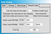
220V has to be connected to the "Gen In" connection on the Sol-Ark. Then it is programmable using the App. Doing that means I won't be able to connect a generator or AC couple to the Sol-Ark.

This is from the manual-

Smart Load (Gen Load) ▪ This mode utilizes the Gen input connection as an output which only receives power when the battery is above a user programmable threshold. ▪ The Gen input breaker in the user area of the system becomes an output to high power loads such as a water heater, irrigation pump, ac unit, pool pump. ▪ Smart Load OFF Batt • Battery voltage at which the Gen load will stop being powered ▪ Smart Load ON Batt • Battery voltage at which the gen load will start being powered ▪ Note: If using Gen load for a water heater, it is recommended that only one leg (120V) be connected to the bottom element. This significantly reduces the power consumption of the water heater while retaining core functionality (it will heat water, only slower). ▪ Note: Gen Load is limited to 40A at 240V (Do not exceed!) • Solar Watts is for on grid. o System waits to turn on smart load until enough PV power is produced (when on grid).

From the App-

1601772418611.png
 
My other concern was the transfer panel only gets 120V from main panel as shown. There's a red wire to a breaker in the main panel, but not a black wire.

Maybe that is an example of how to daisy-chain one existing breaker through, and a similar way would daisy-chain a split-phase 240V circuit? Your drawing has only one example circuit.

I assumed it had a busbar and was fed by a large breaker and fat wire from breaker panel. Maybe not. Maybe a busbar from generator (inverter) and wires from individual breakers in main panel.

Here is what I just ordered:


It is a 100A box, with 100A breaker to feed its busbar from main panel and 30A interlocked breaker to feed from generator cable.
I'll swap that 30A connection for a larger hard-wired circuit from my inverter.

I suddenly lost confidence in 63A transfer switch consisting of two interlocked 2-pole DIN breakers, so I'm replacing it with this one.
 
Here is a manual transfer switch. There are several models, different numbers of circuits:


I don't think you need line-side tap, even with two inverters, because it looks like you have 150A main and 225A busbar. If so, you could have two, 60A PV breakers.
Only benefit of line-side is you could have inverters hooked to the grid and serving as UPS for the entire house. But you might be told you could only have 40A of line-side tap (to avoid overloading utility drop if it fed maximum current to main panel and you had loads on the line-side tap)
Hedges, in post 38 you recommended the Reliance transfer switch to use in place of the one in the picture below.
Since I plan to use the Generator input for load shedding my high load appliances and air conditioning, will I need another transfer switch for that too?
1607972845782.png
By having your inverter connect to main panel with 50A or whatever breaker, and feeding a critical loads panel, you could use interlocked breakers to disconnect from grid and feed main panel with output of Sol Ark. That way any reasonably sized load in the house could be powered if desired. (maybe don't put that in until the rest is finished, to avoid confusing the inspector)
These transfer switches and ac disconnects are confusing the heck out of me.

There is this note from the manual that I am trying to understand as well-
Single System Installs: Install Double Pole 60A breaker in Main Panel for Grid In/Out a. It is best practice to install at the opposite end of the bus bar from the main breaker (Usually this is the bottom of the breaker panel).
 
OK, not 50A but 60A.
Your drawing has the 60A breaker which feeds SolArk at bottom of main panel, and main breaker at top. That is good.

Drawing has the Reliance transfer switch in the middle, looks like circuit "A" can be powered by either main panel or by SolArk.
Reliance serves multiple transfer switches, one per circuit. Each takes care of 2 inputs.

Not sure, but you may be able to daisy-chain two of those transfer switch/breaker in order to select three sources:
(Grid OR SolArk) OR Generator
Thanks Hedges.
Yes, the newer Solark uses 60A.

I will look into 2 circuit inputs on Reliance.
 
Back
Top