shannoniganz
New Member
- Joined
- Jan 24, 2022
- Messages
- 7
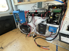
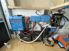
Hi all. I am having trouble with my Victron Inverter/Charger in my new electrical setup. My battery bank is showing a voltage of 13.2 all along the terminals. I have 4/0 cables going from my lynx distributor to my inverter/charger along with the 400amp fuse. I have read the Victron Manual front to back. The problem is that when I power my system on (master switch), nothing happens. My DC power doesn't work, my battery monitor, solar charge controller, NOTHING powers on. The voltage drops at the battery terminals and ALL other connection points to 2.37 volts!! When I disconnect the inverter cables from the lynx, everything works and voltage is consistent with the battery 13.2V... I have DC power and my solar and everything works beautifully (which is a relief since it's a new setup). But I'm beyond frustrated with the inverter charger.. I have tested the cables and I've even made new ones and swapped them out because my first thought was faulty crimps. I've tried everything. I cannot find an answer after days of "google" research in addition to the manual. Now I'm beginning to think there's something wrong with the inverter? It's brand new and has not powered on.. the lights won't flicker or anything. I have a shore power plug wired to it with nothing plugged and a breaker box with the main breaker turned off. I have thought about trying to plug into shore power, but I'm nervous about doing that. PLEASE can someone help me figure out what's going on, it's driving me crazy.
There's a picture of my system attached but note that I've added a second battery since that photo was taken thinking that my battery bank could be the issue. I'm wondering if it has something to do with the BMS, perhaps my batteries aren't charged enough to power the load? How much power does the Multiplus require to turn on? I am getting 13.2V at the terminals though indicating a 70% or so SOC.. but the batteries weren't "resting" for long when I checked that voltage with my multimeter. My SOC on my Victron shunt isn't accurate yet since I just set up my system and haven't had a full charge yet. But I would think that the Victron would still turn on?? I'm going to charge the batteries fully tomorrow to see if that works, but I doubt it at this point.
Here are some specs of my solar electrical system in my camper van:
Victron Multiplus 12V 3000 Multiplus inverter/charger
2x206AH SOK lithium batteries
2x Victron lynx distributor (bus bar system)
1 Victron Orion 30amp DC-DC charger
600 Watts of solar panels
60 MPPT Renogy Solar Charge Controller
Victron Smart Shunt Battery Monitor/other communications devices
 . I just watched Will's video on it: