MrPotatoHead
New Member
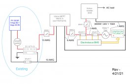
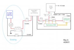
I have nine 230W panels in a 3S3P configuration that are directly powering the lower element in my water heater. It works very well and I have lots of excess power (usually) so I am planning to build an off-grid system using Victron MPPT and inverter. Victron's website suggested the 150/70 MPPT and I think 3kVA sounds like a good number for continuing to power the lower element of my water heater as well as a window A/C unit and other shop tools. I'll basically add loads as long as it stays adequately charged.
I initially used a DC-GFP-63 ground fault protector since I was told that was a good idea. I was never sure if it was necessary and I'm okay with removing it if you suggest I should.
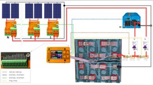
I'd like to know if my layout makes sense, if the breakers at the locations indicated are necessary and what their values should be, if the wire gauges look good, etc., etc. I already have the Electrodacus BMS (the shunts on the + side are according to the manual) and LiFePO4 batteries.
Watching lots of how-two videos makes these systems seem remarkably simple until one starts to actually design one. Then, there are dozens of details to figure out. Thanks for your help.


