再生可能 エネルギー
New Member
- Joined
- Nov 28, 2019
- Messages
- 261
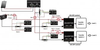
The following schematic represent the Off-Grid Solar system that I am implementing.
I have two specific loads. The first load contains only 120 V LED lights which are mostly used during night time.
The second load will be a 240 V water heat pump to use excess of solar energy, when the batteries will be charged.
I am making my own custom Transfer Switches, because I have some particular specifications, such as using the Solar system as an UPS generator.
Also I try to get my system as efficient as possible by turning off the two inverters when they are not in use.
I am currently designing the 48 V DC wiring diagram and I have few questions.
- 1. I plan to use various DC switches to help when doing some maintenance work, and I wonder if the SW-1 is really needed?
- 2. I plan to use a T-Fuse to protect the battery, but I wonder if I should also add a T-Fuse for the SCC DC output and also to each Inverter?
- 3. I plan to use some Watt-meters shunts, and I wonder if the location and connection of those seems correct?
- 4. This diagram is somehow simplified, and in particular the (-) and (+) bus-bars are not represented. However I am open to any comments.
Thank you.

Last edited:


