diy solar

diy solar

Please Review My Diagram

KCBlues

New Member
Joined
Feb 6, 2022
Messages
25
Thanks to all I have learned here and from reviewing various videos and online forums and Victron videos and manuals, I have drawn up a diagram for a simple 300 watt portable solar system I am planning as part of a change of our trailer's lead acid batteries to lithium and adding a portable solar panel set I built from HQST 100 watt panels. We will hopefully upgrade to a big inverter/charger later, after we can afford an inverter and more batteries and panels.

For now, we just want to help keep the lithium batteries charged enough to run the 12 volt only refrigerator and some lighting. We have a pair of Hondas if we really need to run the AC, or to top off the batteries while boondocking on cloudy days and the solar doesn't keep up.

The trailer's converter is a WFCO Auto-Detect that has the correct charge profile for lithium batteries.

I'd appreciate everyone's input on how I could improve the setup, or if I have anything missing or in the wrong place.

Also, I have a question I haven't seen answered. The Victron solar charge controller has a ground screw on the side that I am not sure exactly where it should be wired to, or how big the wire should be. Do I run it to the travel trailer's frame?

"Chassis grounding
A separate ground path for the chassis ground is permitted because the chassis is isolated from the positive and the negative terminals."

Thanks for all the great advice and knowledge shared here!
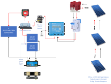
Solar Diagram-6.png

(Edited to update drawing...)
 
Last edited:
You didn’t mention how your panels are to be wired if you have more that 2 panels connected in parallel you need a fuse between each of them.
 
The shunt lines look strange. The shunt just goes anywhere on the (-) battery circuit between the charger/inverter and the battery.

You do not need two circuit breakers on the PV. Just one will make the circuit open, thus disconnecting the circuit.
 
Last edited:
You didn’t mention how your panels are to be wired if you have more that 2 panels connected in parallel you need a fuse between each of them.
Thanks for the info. I'm using MC4 branch connectors to hook up the panels in parallel, then one cable to the double-pole circuit breaker.

So, I need to add an inline fuse on each panel's positive cable between it and the branch connectors?
 
Thanks for the info. I'm using MC4 branch connectors to hook up the panels in parallel, then one cable to the double-pole circuit breaker.

So, I need to add an inline fuse on each panel's positive cable between it and the branch connectors?
Not necessary, you have a circuit breaker there already.
 
Take a look at how I did my trailer setup:

 
Not necessary, you have a circuit breaker there already.
Thanks for the link!

The dual pole circuit breaker is more for a disconnect than circuit protection. The various diagrams I've seen said to use a higher-than-ever anticipated rated breaker so it functions more as a "switch" than as a "circuit breaker".

For safety's sake, I'm adding 15 amp inline fuses to the setup...
Make sure the fuse is not less than the IMP of the panel, otherwise you could be just opening the circuit during normal operation.
 
Make sure the fuse is not less than the IMP of the panel, otherwise you could be just opening the circuit during normal operation.
Thanks! The manufacturer sells a 15 amp fuse holder for the panel. Better safe than sorry!
 
Thanks for the link!

The dual pole circuit breaker is more for a disconnect than circuit protection. The various diagrams I've seen said to use a higher-than-ever anticipated rated breaker so it functions more as a "switch" than as a "circuit breaker".

For safety's sake, I'm adding 15 amp inline fuses to the setup...
If your panels are in series no fuses are needed or desired as the potential amps don’t exceed the capacity of any of your equipment. If you have mor than 2 panels in parallel you need fuses ( or breakers if you use a combiner box) between each of the panels as a internally shorted panel could overeat and cause a fire because the potential combined amperage of the 2 or more connected panels exceed the rating of the shorted panel. This is a rather rare occurrence I’m not even sure there is a documented case of it happening but it is theoretically possible and fusing in this circumstance and is best practice. A double pole switch (over amp breaker) is a good idea because it reduces the chances of shock if servicing the charge controller.
 
If your panels are in series no fuses are needed or desired as the potential amps don’t exceed the capacity of any of your equipment. If you have mor than 2 panels in parallel you need fuses ( or breakers if you use a combiner box) between each of the panels as a internally shorted panel could overeat and cause a fire because the potential combined amperage of the 2 or more connected panels exceed the rating of the shorted panel. This is a rather rare occurrence I’m not even sure there is a documented case of it happening but it is theoretically possible and fusing in this circumstance and is best practice. A double pole switch (over amp breaker) is a good idea because it reduces the chances of shock if servicing the charge controller.
You guys rock. Seriously. Thanks for the input.

I had considered adding fuses, but then checked some of the diagrams and didn't see any in the picture.

What I missed was an explanation from Will in the text that I'd need fuses IF I went with more than two panels in parallel. I knew I needed to post the diagram here before I finalized everything...

I have fuse holders and some spare fuses on order!
 
I’m wondering if you know what the amperage output of your charger/converter is. It’s not unusual for the charge rate to be very disappointing.
 
I was given a small Victron Smart Solar 100/20. It is rated for up to 100 volts and outputs 20 amps. I would have bought a larger one, but free is hard to beat and it can take all the panels can give. They are 100 watt HQST mono panels and have a VoC of 21.6 volts and ISC of 6.5 amps.

We only do occasional boondocking trips, so we just need a small system to keep the 12 volt fridge cold and power some LED lights.
 
If you meant the WFCO converter, it is a WF8955AD, which puts out 55 amps DC and automatically sets the charging profile to lead or lithium.
 
Thanks to everyone for the advice on the fuses and connections.

If anyone has any advice on the grounding of the solar controller, I'd appreciate the input on size of wire and where to ground it.
 
I grounded my victron solar controller with multi strand 8 awg wire with green insulation to the chasis ground in my RV With a grounding bar with one post, #10 self tapping screw, and a star washer. I did not get that from the manual, but from a Samlex inverter manual.


You went with quality parts with Victron, but the other ones you pictured are not quality. The switch you have is not ul listed and if you look closely at the voltage versus amps, it goes down. I like the 350 amp blue sea battery switches. Same thing with the circuit breaker on the left. Seems to be a no name circuit breaker that has failed in other setups. I’m unsure of your DC breaker on the right, but make sure its rated for the DC voltage you plan too use. I prefer midnite solar breakers for dc. They start at 125 volts and go up from there.

Thanks for the info on grounding the MPPT, exactly what I was looking for.

The battery disconnect switch is made by AMPPER and is rated for 600 A continuous at DC 12V, 2500 A momentary at DC 12V. It should more than suffice for such a small system.

That is a Blue Sea Systems 7035 187 Series circuit breaker between the MPPT and the Victron MEGA fuse holder. Thanks to reading all the info here, I knew to go with Blue Sea for "mission critical" breakers like that one.

The DC breaker at the right is just being used as a disconnect, and is rated appropriately.

True, some of the items aren't UL listed. In fact, even the Victron controller isn't UL listed, which frankly surprised me. They all have CE listings, which indicate they at least have passed basic safety testing. While definitely nice to have that added level of testing and approval, UL listing isn't required since the system will never be used as part of a grid-tie system.

Thanks once again for helping point me in the right direction!
 
Your choice of circuit breaker and switch seems perfect. I mistook the pics for something different.

It’s not so much that the stuff is UL listed but tested somehow for DC. I’m sure there’s some sort of rating on the Blue Sea site.
 
Back
Top