moonlitsouls
New Member
- Joined
- Jan 4, 2021
- Messages
- 424


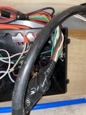
Appears to be correctOk I think I see 2x orange romex going in and something in grey flex conduit.
There appears to be a big black cable that has a lot of wires and a shag-nasty bit of electrical tape.
It looks to be be mangled before it goes into the box.
Is that going into the box?
My guess is one of the bits of romex goes to the generator and the other bit goes to the ac distribution panel, please confirm?
The grey flex conduit probably goes to the inlet, please confirm?
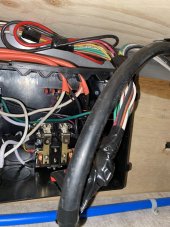
What about the mangled mess of wires and electrical tape?Appears to be correct
I think the grey cord has wiring for the shore power and the generatorWhat about the mangled mess of wires and electrical tape?


Hmm my Inverter is basic , I think it only has positive and negative , what do you mean?Is there continuity between neutral and ground on the inverter.
Shut it off before you test.
Hmm my Inverter is basic , I think it only has positive and negative , what do you mean?
So the positive lead of the multimeter goes into which ?Neutral=wide slot
Ground=round hole
dc {
    * 12 volt system floating
    * ac/dc distro 10 feet round trip to core
    * 75 amp fuse because the dc distribution center backplane is part of the circuit.
    core {
        pos { * littlefuse fhz 7 with fuses over the busbar
            004|150|<->200A_breaker<->battery.pos
            004|150|<-scc.output.pos
            004|150|<-dc2dc_charger.output.pos
            004|150|->inverter.pos
            004|075|->dc_distribution.pos
            016|001|->shunt.pos
        }
        neg { * 4 position busbar
            004|UUU|<->shunt.neg.aux
            004|UUU|->scc.output.neg
            004|UUU|->dc2dc_charger.output.neg
            004|UUU|<-inverter.neg
            004|UUU|<-dc_distribution.neg
        }
    }
    shunt {
        pos
        neg {
            aux
            bat<->bms<->battery.neg
        }
    }
    dc2dc_charger {
        * 60 amp dc2dc charger
        * should be using 2 awg but that big honkin alternator can compensate for the voltage drop
        output {
            pos
            neg
        }
        input {
            pos<-alternator.pos
            neg->starter_battery.neg
        }
    }
    inverter { * 1200w watt inverter
        pos
        neg
    }
    scc { * scc 100/50A
        output {
            pos
            neg
        }
        input {
            pos<-dp_breaker<-panels
            neg->dp_breaker->panels
        }
    }
}with the meter set for continuity.So the positive lead of the multimeter goes into which ?
I'm kind of worried about getting you to test stuff.So the positive lead of the multimeter goes into which ?
0.0 - 0.1 voltsWith the power off test for...
* make sure there is continuity between N and G
91.5 voltsIf the previous test passes...
with the power on test for...
* make sure there is 120V between H and N
0.0 volts* make sure there is 120V between H and G
0.0 volts* make sure there is 0V between N and G

Test continuity not voltage.0.0 - 0.1 volts
That is not good91.5 volts
That is not good0.0 volts
I don't want to integrate the Krieger inverter into your trailer ac domain.0.0 volts
Probably messed something up
Maybe because its a modified sine wave inverter and you have an non-RMS meter.Check this out, I did the test on the extension cord that I have running from the inverter itself because I could get better connections on this Max 96 V
Regarding the inverter, I watched a video today where this guy on YouTube walked through several different scenarios on how to wire an inverter, and the different types of inverters and how they integrate into the RV. At 8:24 you can see him describe “a basic inverter” I believe that fits exactly what my system is. When you say you don’t want to integrate the inverter into the AC panel, I thought we weren’t doing that anyway because I just have a basic inverter that can’t be hardwired?Maybe because its a modified sine wave inverter and you have an RMS meter.
Just a wild guess on my part.


")
