diy solar

diy solar

Portable solar generator

TreeTree

New Member
Joined
Jan 5, 2022
Messages
7
Hello

I am a newbie, I've currently got a chicken coop solar system(1x190w PV, 20a pwm, and a 100ah flooded lead acid battery)

I've been trying to understand how to make a solar generator, watched heaps of videos, made the diagrams, ordered most of the parts, now I'm seeking a second set of eyes to ensure i won't break any of the equipment I've purchased.


Solar generator

2x 250w PV . vmp 18V, voc 22.4V
Parallels. (with 30a circuit breaker on each wire)- or should I only use 1x 250w pv? Worried about overcharging? The mc4 connectors on the solar panel only seem to hold gauge 8, the wire length from PV to controller would be about 4metres, does it have to be gauge 6?

1x 60a PWM with 100amp fuse to the battery

4x 3.2V lifepo4 100ah en series to make 12.8v 400ah battery. Can I get away with using gauge 8 instead of Guage 6?

1x Daly BMS 100a with Bluetooth

1x 200w 12V to ac Inverter (on 50amp fused relay, or will 50a be too big?) Gauge 8 wire or do I have to bite the bullet for gauge 6 wire?

2x 150a bus bars(i wanted a 170amp fuse but can't find one, can i use 200amp MIDI anl gold wafer fuse?)( I would use gauge 8 wire for this ?)

1x 100amp total output fuse block

1x 5 gang switches panel with a cig lighter outlet
I am unsure what size fuse for this switches panel? 1x 15a? The back of the panel comes pre wired with 3x15A fuses.
I realized I needed to put it to the fuse block, but how do I calculate the loads of the switches wires when most the things are on relays? I know a relay only uses .1 amp, do i just combine all the loads of the relays together(minus the "relayed" load)
The bus bar that the fuse block runs off can only do 150amp. 20amp of that is for a fridge, 50amp for inverter, which leaves 80amp usable for the fuse block.

1x 54W led spotlight, run with 10a relay to switches panel.
2-4x LED strip lights run off 10a relay to switches panel. Is it just overkill to wire these to the fuse block for 10a too? Or am I right to double fuse ? I can't seem to get unfused relays in my area - all I can find is 10a, 20a, 50a fused SPST and SPDT automotive relays

1x dual 12vdc cig outlet(in 15a fuse for the 7amp load of the USB chargers listed below)
1x 7amp multi USB charger
1x 2amp voltmeter and usb charger

1x 10amp temp controller with temp probe and 2x 70mmx70mm CPU
2x 50amp Anderson plug (1 for the solar panels input into the solar generator box, 1 for output from the battery for future misc appliances)

1x 50L rolling heavy duty plastic container
2x metal ventilation louver panels(on the box, for air).


I've never done circuits or diagrams, I'm.a total digital art noob but i did try my best to make something up

This project I'm hoping would be complete for a March camping trip

Help would be appreciated so i don't fry my investments into lifepo4 hahahaha

Thanks in advance
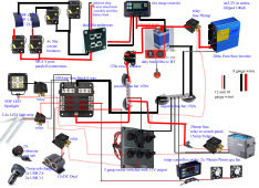
SolarGeneratorWiring (1).png
 
2x 250w PV . vmp 18V, voc 22.4V
Parallels. (with 30a circuit breaker on each wire)- or should I only use 1x 250w pv? Worried about overcharging? The mc4 connectors on the solar panel only seem to hold gauge 8, the wire length from PV to controller would be about 4metres, does it have to be gauge 6?
A 250W panel with a Vmp of 18V would have an Imp of about 13.9A. Two in parallel would be about 28A. With just two panels in parallel you don't need any fuses or breakers. Though it can be useful to have a PV disconnect breaker. You would only need 1 that is at least 30A and can handle 25VDC or more. Since there will only be 28A going from the Y connector to the charge controller, 8AWG is just fine.

1x 60a PWM with 100amp fuse to the battery
You only need a 75A fuse. But you need 6AWG wire to safely handle 60A.

The charge controller should connect to the bus bars, not the battery. Everything should go to the bus bars, not the battery.

4x 3.2V lifepo4 100ah en series to make 12.8v 400ah battery. Can I get away with using gauge 8 instead of Guage 6?
4 3.2V 100Ah cells make a 12.8V 100Ah battery, not 400Ah battery. Things on series add voltage while amps stay the same. In parallel you add amps and keep voltage the same. The wire gauge to the battery is based on the max current going to/from the battery. It has nothing to do with the battery capacity. You have 60A going in via the charge controller. Going out you have the 200W inverter which is only about 20A plus the DC loads which may be up to 65A based on the fuses you show. So plan on a 100A to be safe. That requires 4AWG wire. 8AWG is only good up to 40A. That's much too small for this system. 6AWG might get you up to 70A. That's still too small if you max out the inverter and the DC loads.

1x Daly BMS 100a with Bluetooth

1x 200w 12V to ac Inverter (on 50amp fused relay, or will 50a be too big?) Gauge 8 wire or do I have to bite the bullet for gauge 6 wire?
A 200W inverter at 12V is only 20A. You only need a 25A fuse and 12AWG wire. 8AWG is perfectly safe. Do not use the 50A fuse if you get 12AWG wire. Why a relay? Just use a regular fuse.

2x 150a bus bars(i wanted a 170amp fuse but can't find one, can i use 200amp MIDI anl gold wafer fuse?)( I would use gauge 8 wire for this ?)
150A bus bars are fine. But any fuses/breakers that are ultimately connected to the bus bars must be less than 150A. Fuses/breakers MUST always be the weakest link. Treat bus bars just like any other bit of wire.

Since it was determined that 100A was the max current to/from the batteries you need a 125A fuse (Class-T would be best for LiFePO₄) between the battery and the positive bus bar. That will work fine with the recommended 4AWG wire.

Remember - pick wire to safely handle the max current that will flow through it for the connected load. Then pick a fuse/breaker size that is between the load size and the max safest fuse size for the chosen wire.

As I've stated a few times, 8AWG is too small for many of your connections.

1x 100amp total output fuse block
100A needs 4AWG wire.

1x 5 gang switches panel with a cig lighter outlet
I am unsure what size fuse for this switches panel? 1x 15a? The back of the panel comes pre wired with 3x15A fuses.
I realized I needed to put it to the fuse block, but how do I calculate the loads of the switches wires when most the things are on relays? I know a relay only uses .1 amp, do i just combine all the loads of the relays together(minus the "relayed" load)
The bus bar that the fuse block runs off can only do 150amp. 20amp of that is for a fridge, 50amp for inverter, which leaves 80amp usable for the fuse block.
1x 54W led spotlight, run with 10a relay to switches panel.
2-4x LED strip lights run off 10a relay to switches panel. Is it just overkill to wire these to the fuse block for 10a too? Or am I right to double fuse ? I can't seem to get unfused relays in my area - all I can find is 10a, 20a, 50a fused SPST and SPDT automotive relays
Why all of the relays? As long as the switches are rated for enough amps to control the devices they will be connected to, relays are not needed. What amp rating do the switches have?

The fridge should be connected to the fuse box like all other DC loads.
 
I was just curious as to why you made a selection of getting a PWM charge controller vs just getting an MPPT controller...

Unless there is some specific thing you were trying to achieve in your use-case, I personally kind of see PWM CC's as obsolete (unless it was a money savings kind of choice, where maximum efficiency was not as important for the application).
 
Last edited:
BTW, stay away from the cheaply made circuit breaker from Amazon or Ebay.

Yeah I've found that out the hard way before. Good thing mine never made it to live service, the stupid POS broke the stud out of the housing just tightening it down.

So went and got Bussman HI-AMP series ones instead and they seem to work how you would expect it to. The cheap ones are just made to be look-a-likes but no quality underneath them and I wouldn't trust that they actually hold the power and break at rated point.

Just read some of the reviews on the no name brand ones (I always start by reading the lowest star reviews first and move upwards, so I can read all the horror stories first)...
 
A 250W panel with a Vmp of 18V would have an Imp of about 13.9A. Two in parallel would be about 28A. With just two panels in parallel you don't need any fuses or breakers. Though it can be useful to have a PV disconnect breaker. You would only need 1 that is at least 30A and can handle 25VDC or more. Since there will only be 28A going from the Y connector to the charge controller, 8AWG is just fine.

By pv disconnect breaker do you mean a switch or do you mean a circuit breaker? So just one 30a breaker on the positive to the charger controller.

Thank you for responding in such detail. I learnt alot more.
You only need a 75A fuse. But you need 6AWG wire to safely handle 60A.

The charge controller should connect to the bus bars, not the battery. Everything should go to the bus bars, not the battery.
I can get 70amp or 80amp midi fuses(in ANL holders)
my knowledge tells me 70 might blow through more easily but provide more safety? I can't find 75amp in my area sadly.

I had no idea the charge controller could go to the busbar*, so the charge controller battery output goes to the bus bar that eventually feeds to the battery? I'm not quite sure on using the load output from the charge controller.
4 3.2V 100Ah cells make a 12.8V 100Ah battery, not 400Ah battery. Things on series add voltage while amps stay the same. In parallel you add amps and keep voltage the same. The wire gauge to the battery is based on the max current going to/from the battery. It has nothing to do with the battery capacity.
Blah sorry Im not sure why i calculated that. So 12v 100amp. I hope this is enough for charging phones and running a small tv


You have 60A going in via the charge controller. Going out you have the 200W inverter which is only about 20A plus the DC loads which may be up to 65A based on the fuses you show. So plan on a 100A to be safe. That requires 4AWG wire. 8AWG is only good up to 40A. That's much too small for this system. 6AWG might get you up to 70A. That's still too small if you max out the inverter and the DC loads.
I will get 4awg wire. Will buy 5metres. My internet searches told me the inverter would use 40amps, seems like my searches were so off. I will readjust to run the inverter through the fuse box.
A 200W inverter at 12V is only 20A. You only need a 25A fuse and 12AWG wire. 8AWG is perfectly safe. Do not use the 50A fuse if you get 12AWG wire. Why a relay? Just use a regular fuse.
I thought I had to use a relay because the 25a inverter would be too much current though the switches panel?
150A bus bars are fine. But any fuses/breakers that are ultimately connected to the bus bars must be less than 150A. Fuses/breakers MUST always be the weakest link. Treat bus bars just like any other bit of wire.

Since it was determined that 100A was the max current to/from the batteries you need a 125A fuse (Class-T would be best for LiFePO₄) between the battery and the positive bus bar. That will work fine with the recommended 4AWG wire.

Remember - pick wire to safely handle the max current that will flow through it for the connected load. Then pick a fuse/breaker size that is between the load size and the max safest fuse size for the chosen wire.

As I've stated a few times, 8AWG is too small for many of your connections.
I'll buy the 125a midi fuses, if these are suitable ? Sadly can't find any class T 125a for under $50 or in my country hahaha.
100A needs 4AWG wire.


Why all of the relays? As long as the switches are rated for enough amps to control the devices they will be connected to, relays are not needed. What amp rating do the switches have?

The fridge should be connected to the fuse box like all other DC loads.
The switch panel is cheaper design it says on the listing "12V 20amp". But is this per switch or in total or it is a calculation i don't quite understand? As i thought the fridge and inverter would exceed this 20amp limit?

I want to be able to turn off everything(inverter, fridge, charging ports, led lights) to conserve energy. I was concerned putting all those things through the switches panel would be too much load? I thought relays are the only way to do this in my inexperienced brain?

I'll connect the inverter and fridge to the fuse box on 20 and 25a fuses.

Thank you very much for the breakdowns. I've added the fuses and wiring to my to buy list.

I've been advised to put together and test the system piece by piece(as opposed to plugging it all in and hoping it doesn't blow everything I've connected)
Still awaiting the batteries arrival, first item from AliExpress came after 10 days - which is bizarely quick.
 
I was just curious as to why you made a selection of getting a PWM charge controller vs just getting an MPPT controller...

Unless there is some specific thing you were trying to achieve in your use-case, I personally kind of see PWM CC's as obsolete (unless it was a money savings kind of choice, where maximum efficiency was not as important for the application).
Hi

It was definitely a price point, and 60amp i thought was slightly up sized? But now after learning more I'm not sure sure it was truly oversized for the array

The only other charge controller i have is a Victron 75/15a controller. I'm not sure if it would handle the pV set up? If i could use it it'd be great as it's a safer and more efficient bit of technology than the cheap pwm.
 
12v 100amp. I hope this is enough for charging phones and running a small tv
60a PWM with 100amp fuse to the battery
A 100Ah battery will do that for a while with the TV but it feels ‘crowded’ to my wildhat guess. A second battery would give you some breathing room imho

Cost wise how much did the pwm save you over an Epever mppt for example?
That’s one thing that might help produce more (daylight) power. Since you’re asking about the battery capability I’m surmising that your use is a higher priority concern for you.

On the other hand pwm isn’t useless- it does charge batteries.
 
By pv disconnect breaker do you mean a switch or do you mean a circuit breaker? So just one 30a breaker on the positive to the charger controller.
Most people use a circuit breaker as a PV disconnect between the solar panels and the charge controller. Make sure it can handle the combined amps of the parallel panels and make sure it is rated for the Voc of the panels.

I can get 70amp or 80amp midi fuses(in ANL holders)
my knowledge tells me 70 might blow through more easily but provide more safety? I can't find 75amp in my area sadly.
The Blue Sea Systems 285 series breaker is a good choice. It can also act as a disconnect when needed. As long as you are using high quality 6AWG wire for the charge controller you can use either a 70A or 80A breaker.


I had no idea the charge controller could go to the busbar*, so the charge controller battery output goes to the bus bar that eventually feeds to the battery? I'm not quite sure on using the load output from the charge controller.
Yes, everything to the bus bars.

You don't need to use the load output at all. It can be used for a single low-amp load but with everything else you will have in place you do not need it at all.
So 12v 100amp. I hope this is enough for charging phones and running a small tv
12V 100 amp hour (Ah). It all depends on how many watts the TV and charges use and how much you use them in a day.

My internet searches told me the inverter would use 40amps
You stated it was a 200W inverter. 200W / 12V / 0.85 = 20A. A 400W inverter at 12V would use 40A. The picture of the inverter in your diagram shows 300W which would be 30A.

I thought I had to use a relay because the 25a inverter would be too much current though the switches panel?
Why would the inverter go through the switches panel? Doesn't the inverter have it's own power switch?

I'll buy the 125a midi fuses, if these are suitable ? Sadly can't find any class T 125a for under $50 or in my country hahaha.
No, do not use MIDI fuses for LiFePO₄ batteries. Given your one 12V battery you can use an ANL fuse.

The switch panel is cheaper design it says on the listing "12V 20amp". But is this per switch or in total or it is a calculation i don't quite understand? As i thought the fridge and inverter would exceed this 20amp limit?

I want to be able to turn off everything(inverter, fridge, charging ports, led lights) to conserve energy. I was concerned putting all those things through the switches panel would be too much load? I thought relays are the only way to do this in my inexperienced brain?
Post a link to the switch panel. I don't know if it's 20A per switch or total without seeing it.

Your diagram shows the fridge is 15A so that wouldn't need a relay assuming the switches are 20A each.
The inverter should have its own power switch.
You don't need a switch on the 12V power plug. Just don't put anything into the plug to avoid using any power.
You don't need a relay on the lights since they are low amp.

You may want to add a master switch between the battery fuse and the positive bus bar. Then you can turn off the whole system with one switch. That would be good when you are not going to use the portable generator for a few days or more.
 
This seems awfully complicated for a 100Ah portable solar generator.
Honestly i don't have enough money for what I truly want to do

But i do want to learn the skills with a lower cost system before doing a big system.

Planning to go off-grid in a few years(having been off grid previously, but never made my own large PV System). I think it's best to start small, think big, then move to higher stake and more expensive things. Yes I've made it complicated, but i already have a super simple set up on my chickens coop that runs fans, automatic coop door and lighting. I wanted to challenge myself.

In the future would want to do a 4-5kw 48V system. I think this is a good medium between super simple and more difficult set up. Plus I've learnt much more than if I'd just taken a diagram from someone else and plug and played. Maybe that's my autism tho.
Hope this makes sense.
 
Most people use a circuit breaker as a PV disconnect between the solar panels and the charge controller. Make sure it can handle the combined amps of the parallel panels and make sure it is rated for the Voc of the panels.


The Blue Sea Systems 285 series breaker is a good choice. It can also act as a disconnect when needed. As long as you are using high quality 6AWG wire for the charge controller you can use either a 70A or 80A breaker.


Ah thank you. I'll get that for sure. And it looks like it'll arrive in time too!
It seem the blue sea system is very popular here.
I'm planning to use KnuKonceptz wiring


Yes, everything to the bus bars.

You don't need to use the load output at all. It can be used for a single low-amp load but with everything else you will have in place you do not need it at all.

12V 100 amp hour (Ah). It all depends on how many watts the TV and charges use and how much you use them in a day.
Sorry I forgot to add ah i am not this stupid i promise hahaha
I was planning to do phone charging and device charging during the day, minimize loads over night time to just the tv and lights. Turn off all the USB chargers etc. Hoping to get away with 1 movie a night.

You stated it was a 200W inverter. 200W / 12V / 0.85 = 20A. A 400W inverter at 12V would use 40A. The picture of the inverter in your diagram shows 300W which would be 30A.


Why would the inverter go through the switches panel? Doesn't the inverter have it's own power switch?
It does, i just wanted to make it look seamless and add some accessibility for myself so i don't need to open the box as often to turn off the inverter. But i will ditch the relays on your suggestion - i can learn this skill another time more suitable.
Yes it's only 200w, couldn't seem to find a photo on the PC i was using to edit the photo jaja.

No, do not use MIDI fuses for LiFePO₄ batteries. Given your one 12V battery you can use an ANL fuse.
Post a link to the switch panel. I don't know if it's 20A per switch or total without seeing it.

US $24.55 15%OFF | Waterproof Circuit Breaker Yacht Boat Switch Panel 12v Marine Car 5 Gang Rocker Switch Panel Led + Cigarette Lighter Plug

It's seriously not clear on the item page to me what it's capacity is sadly. Or I'm missing it somehow.

Your diagram shows the fridge is 15A so that wouldn't need a relay assuming the switches are 20A each.
The inverter should have its own power switch.
You don't need a switch on the 12V power plug. Just don't put anything into the plug to avoid using any power.
You don't need a relay on the lights since they are low amp.

You may want to add a master switch between the battery fuse and the positive bus bar. Then you can turn off the whole system with one switch. That would be good when you are not going to use the portable generator for a few days or more.
I'll use the blue seas breaker as the switch?
I'm hoping to utilize it as a way to reduce my power bill(when not camping) for charging devices and using small tools outside (like a soldering iron for projects in the backyard, or clippers for cutting my hair - what can I say I'm an outdoor lover). But always helpful to have a way to safely store without affecting the batteries super badly. Although ultimately i don't like batteries "sitting".

Thank you for all your wisdom.
I'm going to do another digital edit to comprehend and put into a picture all the suggestions you've given me. I think making the diagram just helps me solidify what I'm doing better than copying someone else's diagram.
 
A 100Ah battery will do that for a while with the TV but it feels ‘crowded’ to my wildhat guess. A second battery would give you some breathing room imho

Cost wise how much did the pwm save you over an Epever mppt for example?
That’s one thing that might help produce more (daylight) power. Since you’re asking about the battery capability I’m surmising that your use is a higher priority concern for you.

On the other hand pwm isn’t useless- it does charge batteries.
It was a mistake i bought the pwm. It was an AliExpress item that looked like an MpPt, but then after I bought i looked more closely and it was given a misleading title and was actually pwm. Annoyed but not the worst thing to fuck up i guess. In the future would probably get a Victron instead.
The pwm ended up being $22 Australian dollars
As i recall i bought my 15amp Victron for $150 about 6 years ago. - it's beautifully heavy and sturdy.
 
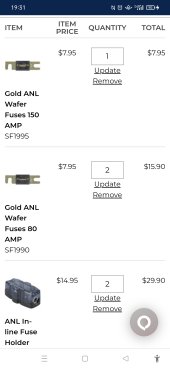
I'm having serious issues finding the sizes of fuses available. It's like the whole of Australia has gone on a hobby spree and all the fuses are out of stock or can't even get the sizes

I could only find 1 x 150a. Not even 2 which is annoying.

Screenshot_2022-01-14-19-31-20-08_40deb401b9ffe8e1df2f1cc5ba480b12.jpg
 
ANL fuses are not rated to interrupt lithium discharge rates.
In the event of a hardware failure, and dead short, ANL won’t stop the arc. T-class will. At 12ish volts it isn’t AS critical, but keep it in mind.
 
I'm planning to use KnuKonceptz wiring
Bad idea. That's copper clad aluminum. You want pure copper wiring only.

Waterproof Circuit Breaker Yacht Boat Switch Panel 12v Marine Car 5 Gang Rocker Switch Panel Led + Cigarette Lighter Plug
I don't see any mention at all about the switch amperage. There's no mention of 20A anywhere on that page. I just see that it has 3 15A fuses but it's not clear what the fuses are for. I suggest finding a better switch panel that is actually properly documented and has switches that actually meet your needs.

I'll use the blue seas breaker as the switch?
No. For a master switch you should use something like the Blue Sea System master switch:


#6006 is a common choice.
 
better switch panel that is actually properly documented
This and the other two points rmaddy mentioned are the three places where scrimping on quality can cost you- with a fire it can cost you a lot! Trade shorts on Wall Street but don’t do shorts in electrical. Both are risky but only one can kill somebody.
 
I've got 1 325W Mission Solar mono panel, a cheap mppt solar charge controler 12V 100A, 2 12V lead acid deep cycle batteries, 6 gauge TTHN wire, 1 1,000W inverter, 1 6,000W 220V inverter, various fuses, bus bars, rocker switches, 1 120V switch, 1 wp receptical, 1 110V/100A meter, 1 12V/10A meter, various gauged wire 10-14 TTHN, 3 cheapo 65W poly and 1 cheapo 85W solar panel.
How should I best incorporate these into a solar charger that fits into a large plastic bin (16" wide x 36" long x 20" deep)?
2 GA wiring batteries in parrell and battery to inverter (1,000W)
 
Back
Top