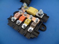
I've been building a house power system based on Will's 400W Solar Power w/ Alternator blueprint and, as the title states, I think I may need to expand beyond Will's original design. Our implementation leverages two SOK 100Ah batteries connected in parallel. At present, the main positive battery terminal has three distinct ring connectors - One for the positive parallel cable, one for the primary battery positive cable, and one for the Renogy Battery monitor. The photo below should give you a good indication of what that currently looks like.
(Please disregard the dangling black cable in the background. It's for a temperature sensor that has yet to be mounted in its permanent location.)

In addition to the above, we also intend to install a Victron IP22 AC to DC charger to be leveraged for occasional shore power charging. My original thought was to connect the IP22 directly to the main Positive and Negative Battery Terminals and call it a day. But now I'm not so sure. The positive stud seems to have plenty of thread left so my original setup should work, in theory. But I am open to suggestions, particularly if there is a a better and/or safer way of doing things.
Or maybe I'm just over thinking this.... Thanks in advance for your feedback.
(Please disregard the dangling black cable in the background. It's for a temperature sensor that has yet to be mounted in its permanent location.)
In addition to the above, we also intend to install a Victron IP22 AC to DC charger to be leveraged for occasional shore power charging. My original thought was to connect the IP22 directly to the main Positive and Negative Battery Terminals and call it a day. But now I'm not so sure. The positive stud seems to have plenty of thread left so my original setup should work, in theory. But I am open to suggestions, particularly if there is a a better and/or safer way of doing things.
Or maybe I'm just over thinking this.... Thanks in advance for your feedback.