Hi all, I have started out on a project to power my pond and ancilliaries which are on 24/7. I've already replaced both pumps with much lower wattage versions and expected total draw is around 400 watts (2 x pumps , UV, Camera , Drum filter)
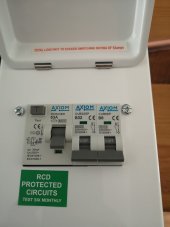
Power is currently provided via a shed which is powered from the main house via armoured SWA and a 2 circuit consumer unit

This where I am now, the gap on the left is for a Victron Multiplus 24/800 and outside there will be 2 x 360W panels
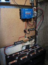
8 x 200aH cells, Smartshunt, Overkill BMS, bit of wire tidying left!
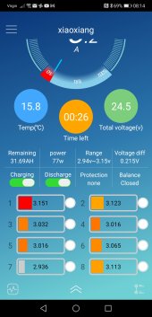
Only panicky moment was when moving the wiring I dislodged a bad crimp and the BMS showed all cells at 0.1V
Will never use the crimp on a wire cutter again and redid all of them with a ratchet crimper

On the AC side I plan to "Hijack" one of the circuits from the exisiting CU and put that in a brand new mini CU isolated from the house AC

Once I have the inverter/charger I plan to use scheduling since in the UK there are tariffs where elecrticity is much cheaper e.g. between 20.30 - 01.30 it is one third the price
Pond inhabitants:

Power is currently provided via a shed which is powered from the main house via armoured SWA and a 2 circuit consumer unit

This where I am now, the gap on the left is for a Victron Multiplus 24/800 and outside there will be 2 x 360W panels
8 x 200aH cells, Smartshunt, Overkill BMS, bit of wire tidying left!
Only panicky moment was when moving the wiring I dislodged a bad crimp and the BMS showed all cells at 0.1V
Will never use the crimp on a wire cutter again and redid all of them with a ratchet crimper

On the AC side I plan to "Hijack" one of the circuits from the exisiting CU and put that in a brand new mini CU isolated from the house AC

Once I have the inverter/charger I plan to use scheduling since in the UK there are tariffs where elecrticity is much cheaper e.g. between 20.30 - 01.30 it is one third the price
Pond inhabitants:

Last edited:


