diy solar

diy solar

Practical implementation of a MPPT algorithm

rin67630

Solar Enthusiast
Joined
Apr 29, 2020
Messages
1,067
Location
Nort-Rhine-Westphlia Germany
Hi,
the Perturb and Observe MPPT algorithm is well known and mainly works OOB.

I think a very few people did really really test how their implementation works under every possible situation.
I am looking to share experience about how to implement it to be as efficient as possible.

- How frequently should it run?
- What is amount of increments that gives you the best results?
- What are the other factors to get it running without oscillations ( e.g. constraining the output)
- What kind of set-point follow-up do you implement, in case of a voltage/ current limitation of the output?

I developed a plotter to plot:
the Panel voltage Vin,
the MPPT-modified Vin setpoint,
the output current Iout,
the corresponding output current setpoint

And have been observing my system (and also commercial ones) under various weather conditions.
Here are my current findings:

a) There is a difference, if you use a lead-acid battery vs a LiFePo one (with FLA, the SOC is more prone to oscillate)
b) Under bright sun, when the panel is partially shaded (e.g. by a tree/ building) many systems (also commercial ones) begin to oscillate since some cells deliver full power and the other ones add internal resistance.
-One can see if only half of the panel is shaded (oscillating between Vmp and Vmp/2)
-Or if both halves of the panel are shaded (oscillating between Vmp and ~the battery voltage)
c) there is a major difference, if you run panels with a MPP just 30% above the battery voltage or panels having at least twice the battery voltage.

These oscillations (sometimes at the pace of only a few seconds) remain mainly unnoticed and only last as long, as the shading occurs.
But during this oscillation phase, the harvesting is strongly reduced and the Perturb-and-Observe algorithm is... perturbed.

One can do better!

For my DIY system, I have developed an anti collapse mechanism:
I keep a trace of the last good panel voltage and am detecting the collapse by comparing the voltage to the last sample (every second)
if the voltage drops by 5V in one second, am reacting by:
- a) restoring the panel voltage set-point to the value it had before the collapse +1V,
- b) halving the the current setpoint to give a relief to the panel and enabling a restore from the bottom.
With that strategy I can fight oscillations pretty efficiently, a collapse is restored within 10 seconds.
That is also working pretty well, with scattered clouds on a windy day, where the panel irradiation change continuously and provokes collapses.
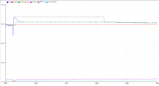
1624374867808.png
the plot runs at one pixel per second.
-Blue is Vin,
-Green Vin Setpoint,
-Red a fixed reference SetPoint (no impact in the process, just underlining the Vin variations)
-Orange, is the Output Current and
-Violet the Output Current SetPoint,
-Cyan has no signification.

I would love to hear from your personal experience.
Regards
Laszlo
 
Last edited:
I have now refined my anti-collapse mechanism:
Immediately after a collapse, I cut the power for a few seconds and read the Voc.
Then I set the Vin value to an adjustable percentage of Voc (e.g. 90%) and keep it at that value for 5 minutes, after that I return to MPPT.
This effectively prevents oscillations, which happen in the morning when the panel is partially shaded by buildings and the power increases from 20% to 80% in 20 minutes. This could also happen during the day if you can't avoid shading from chimneys or if scattered coulds are rapidly and repetitively changing the irradiation.
MPPT is fooled by these conditions.

1624778401849.png
 
While I haven't implemented or measured any MPPT algorithms, I understand some do a better job of finding Vmp in the case where curve is not monotonic from Voc to highest Vmp. If PV panels are wired series/parallel and some panels are shaded, a simple algorithm that just draws down voltage until power peaks and starts to decline misses a higher wattage peak at lower voltage. Some algorithms periodically sweep the voltage lower to find such operating points.
 
I have not gone beyond reading a few papers on MPPT. I seem to recall that papers took product of volts and amps to determine MPPT. Back then I thought to myself that monitoring current may be all that is necessary. Wouldn't the highest current point also realize the maximum power point?
 
I regret mppt like smart victron mppt can't setup a minimal voltage power point and learning from 7 past days what is the real range of mppt voltage.
Same for maximal voltage power point, and maybe some larger trial once a week when output current is high in order to reveal some wiring loss or solar pannel damage
 
I have not gone beyond reading a few papers on MPPT. I seem to recall that papers took product of volts and amps to determine MPPT. Back then I thought to myself that monitoring current may be all that is necessary. Wouldn't the highest current point also realize the maximum power point?

Highest current point is Isc. Maximum amps x zero volts = zero power.
The curve hits zero in two places; objective is to find the maximum.

Just like the "matched impedance provide maximum power transfer" we were taught in school. And proved by taking the derivative.
Then I met a PhD and company fellow who actually believed it and used it in his work. I explained why he was wrong (I like to do that!) in the particular application, and his calculation of power was not correct.
 
All mptt that range over "V range" are simply bad algorithm. The range can be learnt (local topology, daytime) and reduced to a minimal range for looking the best power point as fast as possible

main-qimg-253a31d1bb4fcf60c6c1cda65785e92a
 
I regret mppt like smart victron mppt can't setup a minimal voltage power point and learning from 7 past days what is the real range of mppt voltage.
Same for maximal voltage power point, and maybe some larger trial once a week when output current is high in order to reveal some wiring loss or solar pannel damage
Learning from 7 past days would not help. Every day is different.
The range of MPPT voltages depends on many factors:
- Panel temperature
- Irradiation
- Partial shades
- Micro cracks un some cells
- Angle to the sun
- Diffuse-sharp light
- And -last but not least- the chemistry/shape of the battery.
Weak batteries/lead-acid are reacting on charging current changes with voltage changes, that impacts the conversion.
Especially if the delta to Vmp is not that large.
 
All mptt that range over "V range" are simply bad algorithm. The range can be learnt (local topology, daytime) and reduced to a minimal range for looking the best power point as fast as possible

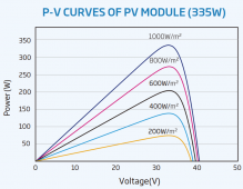
main-qimg-253a31d1bb4fcf60c6c1cda65785e92a
Good picture!
It misses the G=80W/m² curve corresponding to a rainy day.
The Vmp is then below 14.4V and a lead-acid battery cannot charge fully.
Even less with a MPPT Scc that needs 3V deltaV to operate and ceases to function at G=500W/m² with 18V class panels.
 
first thing
Good picture!
It misses the G=80W/m² curve corresponding to a rainy day.
The Vmp is then below 14.4V and a lead-acid battery cannot charge fully.
Even less with a MPPT Scc that needs 3V deltaV to operate and ceases to function at G=500W/m² with 18V class panels.
i disagree victron mppt have a boost module to take advantage of inductance of solar long cable and are able to stepup voltage before step down
 
first thing first, you have to determine the real number of cell on your solar string and the probability that a portion is shaded by obstacle function of day time; here is the 7day history usage.
There is no secret, look-for mppt take time and the less range you have to look-for faster response you can.
I think mppt algorythm try by test and error, often use small step and some time try bigger step to not be jail in low power point.
Smart device know clouds don't go away in minutes and choose to make bigger step than sunny time.
Bad algorythm don't determine if there is clouds or shaded time (history)
 
first thing

i disagree victron mppt have a boost module to take advantage of inductance of solar long cable and are able to stepup voltage before step down
"a boost module to take advantage of inductance of solar long cable"

???
can you please elaborate on that?
Which Victron SCC do you speak of, and what is "taking advantage of inductance of solar long cable"? Please explain!
 
"a boost module to take advantage of inductance of solar long cable"

???
can you please elaborate on that?
Which Victron SCC do you speak of, and what is "taking advantage of inductance of solar long cable"? Please explain!
If you teardown (not easy) a bluesolar mppt 100/50 there is 6mosfets, two at the first stage as sync boost topology (wire is inductor here) and 4 mosfets (halfbridge) in dual buck topology with dual inductor. Using inductance of wire is good to avoir capacitors at solar input and solve the ripple current input at the dual buck module
 
Isc is usually lower than Imp.
And it varies very largely with the outside conditions.

Isc is the current produced when PV leads are shorted (zero volts)
Voc is the voltage when PV leads are open circuit (zero amps)
Imp is the current produced at some voltage between zero and Voc, and is always lower than Isc.
Isc of course occurs at lower voltage than Imp, at zero volts.

For instance, this 310W panel lists Impp 9.40 A, Isc 10.03 A


(See table, also I-V and P-V curves)

Yes, the current varies as shown in the curves.
 
If you teardown (not easy) a bluesolar mppt 100/50 there is 6mosfets, two at the first stage as sync boost topology (wire is inductor here) and 4 mosfets (halfbridge) in dual buck topology with dual inductor. Using inductance of wire is good to avoir capacitors at solar input and solve the ripple current input at the dual buck module
??? I cannot really believe that.
It would mean that with short wires, the mosfets would short the panel?
The would also mean that the external wires would carry the huge current pulses of the boost conversion and become powerful antennas for massive RF interference.
Never would any FCC accept such a design!
Were did you get that info from?
Aren't the two mosfets at the input just the usual ideal diode for a flowback protection?


I don't know how confident one can be with this data sheet.
That figure would suggest that Vmp is constant over the full irradiance span.
1624887954091.png
It is generally admitted that Vmp decreases as G decreases.
 
Last edited:
I had to implement an automatic panel disconnect on my controller because under some shade conditions the algorithm just gets lost. A 60V array can drop down to the low 20's and below. A short disconnect will pop it back up to over 50V at four times the power. Every controller should have a minimum voltage setting. I've found that a temperature based power point voltage in shade isn't that much worse than what MPPT finds at a lower voltage. FLIR images of panels at high loads and reduced voltages shows concerning heating of weaker cells. This makes you think long term it will lead to failure.
 
I don't know how confident one can be with this data sheet.
That figure would suggest that Vmp is constant over the full irradiance span.

It is generally admitted that Vmp decreases as G decreases.

Most manufacturer graphs I've seen do resemble that. It appears a line through peaks would be vertical. In real world, the higher wattage peak would have more heating so more current leaking through the photodiodes, which could shift Vmp to a lower voltage than what 25 degrees C gives (but lower illumination could be at still lower voltage). I think these graphs represent lab conditions, but likely don't have enough data points to actually represent measurements. Rather, a curve-fit to a small number of data points. Would like actual Vmp/Imp of each to be represented but that probably isn't the case. Since the lab test is a flash test with panel at 25 degrees C, can't perform an MPPT algorithm, just step through voltage or current with an electronic load.

SMA ran a test with two PV strings of different orientations connected in parallel. That meant as the sun passes overhead, they get peak sun at different times. The power harvested was 2% less than when each PV string had its own MPPT. This means that forcing them to the same voltage moved them off their peak Vmp, Imp operating point, but total effect was minimal over the day.

I'm not sure how scientific their test was, but it was real-world. If they had used two inverters vs. one, differences in efficiency vs. power output of the inverters would skew results. But, their recent model inverters have two or three MPPT, which may be ganged. So if they connected PV string #1 to MPPT #1 and PV string #2 to MPPT #2 and conducted tests with/without bridging the two together, that should be valid. Operated with sun rather than lamps in a laboratory, would have to repeat each multiple days and measure sun intensity, make sure difference was due to weather. Or, implement the two cases side by side, also swap configurations on some days to average out equipment differences.
 
Last edited:
I had to implement an automatic panel disconnect on my controller because under some shade conditions the algorithm just gets lost. A 60V array can drop down to the low 20's and below. A short disconnect will pop it back up to over 50V at four times the power. Every controller should have a minimum voltage setting. I've found that a temperature based power point voltage in shade isn't that much worse than what MPPT finds at a lower voltage. FLIR images of panels at high loads and reduced voltages shows concerning heating of weaker cells. This makes you think long term it will lead to failure.

That sounds like, due to shading MPPT found a peak with some cells producing maximum current but forcing that current through other (likely shaded) cells. Then when sun returned to those cells, MPPT didn't find the higher peak at higher voltage because there was a local minima between them.

Some MPPT periodically (about ever 2 minutes) run a sweep to see if other voltages have higher peaks, to avoid being trapped at local maxima.

We usually think of shaded panels getting bypassed by current through a diode. What voltage does it take to force current through a cell?
The following paper has a graph showing more than 30V to force even 0.2A. But at lower voltage you might see within a diode-bypassed portion (perhaps 15 Voc), like if a single cell was shaded, about 50 mA could be drive. 50 mA x 15V = 0.75W, which doesn't seem excessive to be dissipated by one cell. Obviously if a long string had no bypass diodes it could cook shaded cells. Perhaps it depends on uniformity to withstand moderate reverse bias, not develop hot spots.


"Cells were reverse-biased at power levels of one to four times the maximum power point (MPP) rating."
Which might be at excessive voltage. Forcing power dissipation by a reverse-biased diode would mean raising voltage until it carried enough current for target power, then reducing as cell heats up and carries more current. In a panel, voltage would be limited to Voc of other cells in that diode-bypassed section. Current would be limited to Isc but not expected to get that high.
 
Back
Top