diy solar

diy solar

prime the caps in my inverter by connecting it directly to my converter

All the parallel MOSFET's in the BMS series switch have a very large gate capacitance and drain to gate capacitance. When turned back on after a BMS shutdown event the gate driver circuit will take some time to get the MOSFET's gate voltage up to produce the series switch lowest resistance state. It will not be a well controlled ramp up but it will result in the MOSFET series switch having a softstart like effect.

In most cases this should be enough of a ramp down in series resistance that a BMS reactivation will not cause enough current surge to trip the DC breaker while charging the inverter capacitors.
 
Last edited:
The most likely reason for the BMS to shut off discharge is if the battery or cell is too low.

Not so sure about that. You want to avoid BMS shutting down because it removes all power to inverter and perhaps your battery monitor. Inverter low battery shutdown should be setup to shut down inverter output before BMS low battery does.

To me, especially with a low cost BMS marginal series pass MOSFET resistance, the most likely reason for BMS shut off is the temp sensor on the BMS shutting it down because BMS got too hot from high current drain from inverter.
 
Last edited:
Not so sure about that. You want to avoid BMS shutting down because it removes all power to inverter and perhaps your battery monitor. Inverter low battery shutdown should be setup to shut down inverter output before BMS low battery does.
All true. And that is what I try to set up.

To me, especially with a low cost BMS marginal series pass MOSFET resistance, the most likely reason for BMS shut off is the temp sensor on the BMS shutting it down because BMS got too hot from a few minutes of high current drain from inverter.

OK.... but I have not had that experience. Part of the reason fro that is that when I use a FET based BMS, I try to get one that is rated for double the expected max continuous current).
 
Yep, or
All the parallel MOSFET's in the BMS series switch have a very large gate capacitance and drain to gate capacitance. When turned back on after a BMS shutdown event the gate driver circuit will take some time to get the MOSFET's gate voltage up to produce the series switch lowest resistance state. It will not be a well controlled ramp up but it will result in the MOSFET series switch having a softstart like effect.

In most cases this should be enough of a ramp down in series resistance that a BMS reactivation will not cause enough current surge to trip the DC breaker while charging the inverter capacitors.

Unless they use a very very weak gate driver the switch time would be in a few dozens of µs at most, with the mosfets in the linear region for even a shorter time, so the soft start effect would be negligible IMHO.
 
For inverters larger then about a 300 watts, any ON/OFF switch within inverter will be just shutting down the electronics controlling the inverter's MOSFET's drivers. They do not use a large and expensive switch (ie. your DC breaker/switch), so capacitors are always on the battery lines coming into the inverter.

For a 3kW to 8kW inverter they typically have 7,000 to 10,000 uF's consisting of several paralleled capacitors. Throwing 48v on these caps is not that tough on caps. They are more stressed by the constant ripple current of normal inverter operation, but the large charging surge current is hard on the DC breaker if it is used to turn on inverter. It causes pitting on its contact surfaces, like little spot welding pock marks that can increase breaker switch resistance and eventually cause it to start arcing on large inverter current draw. High surge current could cause the breaker's contacts to stick together by the spot welding action and not allow the breaker to pop open for its primary safety function. And there is aways the possiblity the high surge current immediately pops the breaker back open compounding the pitting process.

Discharging time on these caps is variable depending on models of inverter. Some inverters put a couple mA current bleed resistor across these caps to accelerate their discharge time. A day or more to as little as 5 minutes might not be unexpected.

BMS with MOSFET as series cutout switch doesn't have the problems of mechanical contacts, but another good reason a solenoid contactor cutout is a bad idea. There might be a small possiblity that when the BMS switch re-engages there is enough surge current created to pop the DC circuit breaker. I would expect the series resistance of BMS MOSFET's, battery line resistance, DC breaker resistance, and any current shunt resistance is normally enough to prevent popping circuit breaker. If you have this problem your DC breaker amperage size is probably not high enough or breaker is defective.

This info made me wonder about my 3kw inverters. Both 48v 3kw inverters.

My WZRELB HF inverter definitely sparks and makes a pop that is impressive after being disconnected from the battery for a week or so. Now I always use a precharge resistor if it’s been disconnected for more than a couple days.

My Sigineer LF inverter seems different. I left it disconnected for a couple weeks then reconnected yesterday without a precharge. No spark or pop. Does the huge transformer help somehow?

Anyway thanks for sparking the idea (see what I did there) to try the Sigineer without precharge. I may learn something ?
 
  • Like
Reactions: Vin
My Sigineer LF inverter seems different. I left it disconnected for a couple weeks then reconnected yesterday without a precharge.

That is very interesting. Even LF inverters have the capacitors. If you are correct, it would be the first one I have ever heard of that did not have a capacitor bank directly across the DC.
 
That is very interesting. Even LF inverters have the capacitors. If you are correct, it would be the first one I have ever heard of that did not have a capacitor bank directly across the DC.

I did not mean to imply there was no capacitor.

Just an observation that I don’t understand.
 
If there's absolutely no load on the caps then they probably stayed charged (especially with some dielectric absorption in addition to that) enough to not have a huge inrush current when you connected the inverter.
 
Without capacitance across battery line at inverter DC input, the battery cable inductance would cause high frequency transient voltage spikes that would eventually destroy the inverter MOSFET's. It would also drive the feedback control system crazy trying to figure out what inverter PWM drive is correct for matching incoming DC voltage level to the output AC voltage and power requirement.

It is the job of the caps to remove high frequency voltage transients caused by DC cable inductance. Also the reason to tape battery lines together in parallel to minimize the battery line inductance as the greater the line inductance the greater the ripple current on the filter caps which can destroy them over time.
 
Last edited:
If there's absolutely no load on the caps then they probably stayed charged (especially with some dielectric absorption in addition to that) enough to not have a huge inrush current when you connected the inverter.

Good to know that I can go over 2 weeks without the caps discharging then if that’s true.
 
Last edited:
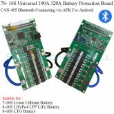
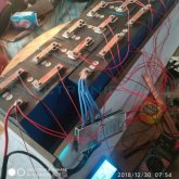
I was examing BMS's on ebay and came across a 16s 320 A with Bluetooth data link that had some interesting pictures.

It has 7 back to back series pass pairs on top side and another 7 back to back pairs on backside for 14 total pairs in parallel.

The interesting thing I noticed is an extra single MOSFET with series resistor at end of series high current switch MOSFET's going to Drain center bus.

Since this extra MOSFET is on the battery connection side it is intended for softstart surge current limiting. One of the parallel resistors is 1.0 ohm but it is hard to make out the multiplier color on second parallel resistor, either 5 ohm or 0.5 ohm..

So this extra MOSFET fires up a few hundred microseconds before turning on the 14 parallel high current pairs providing a maximum 50-90 amp softstart current to charge inverter capacitor.

First unit I have seen with softstarter. It also looks to have a temp sensor on a flex over the series pass MOSFETS.
 

Attachments

  • 16S high current BMS.jpg
    16S high current BMS.jpg
    120.3 KB · Views: 10
  • 16S 320A current BMS.jpg
    16S 320A current BMS.jpg
    106.4 KB · Views: 11
That BMS is the ANT BMS. An 8S version of it was reviewed by @Will Prowse quite a while back. I installed an 8S ANT bms at a cabin a few weeks ago. I can't say I have a lot of history with it but it seems to work pretty well.

Good catch on the pre-charge. I think you are correct. When I was first setting it up, I had the battery type wrong and while I was futzing around trying to figure it out I got an error message that said something about the pre-charge current was too high. That made me wonder if it had pre-charge built in but by the time I figured out I had the battery type wrong and corrected it, I forgot about the pre-charge and never followed up.

My main gripe with the ANT BMS is how to turn it on after you set it up. There are two options:

1) Apply a charge to the batteries.
2) Apply 3.2-5 Volts to the on/off wires.

@Will Prowse also found that the two on/off wires need to shorted together after you apply the voltage.

I ended putting in a DPDT switch that will connect the two wires to one of the cells in one position and short the two wires together in the other position.
 
BTW: It may not be as bad as I make it sound. The most likely reason for the BMS to shut off discharge is if the battery or cell is too low. Many (Most?) BMS's will not turn back on till the battery gets charged to an acceptable level. I have not played with it, but I suspect whatever is charging the battery enough to turn the BMS back on will also charge the inverter capacitors. Consequently, there should not be a surge when the BMS turns on.
But doesn't the inverter remain "off" until the set point is reached and then turns "on", allowing a fresh inrush to the caps or is the circuit of the inverter receiving a trickle say from the PV while the batteries are charging? And all of this is to say no human intervention when the inverter had a low voltage shut down, which of course is a real possibility.
 
The capacitors are always on the DC input side of the switch and control circuit. Consequently, the capacitors will charge even if the inverter has turned itself off. If the low voltage cut-out-recovery of the inverter is higher than the low voltage cut-out-recovery of the BMS things will turn back on in a controlled manor and not have an in-rush.

Starting from the BMS having cut out, (and therefor the Inverter also cut out).
1) A charge source (such as PV ) turns on and starts charging the battery.
At this point the voltate is still too low for both the BMS and the Inverter. However, the batteries and inverter capacitors start charging. The inverter might start drawing some small current to run it's controlls, but the invert function will still be off because the voltage is below the low voltage cut-out-recovery.

2) The batteries charge enough for the BMS to turn on.
At this point the voltage is still too low to turn on the inverter function. The batteries and Inverter Capacitors are still charging.

3) Eventually the batteries (and capacitors) are at a high enough voltage to turn the inverter function back on.

Note: Once the inverter function turns back on, if there is a large load on the inverter, it might quickly drain the battery and cut back out. This is why it is a good idea to set the 'low-voltage-recovery' voltage of the inverter somewhat higher than the low-voltage-cut-off voltage (if the inverter allows it)

Warning: I was recently made aware that on Cotek inverters, if you connect the batteries while the inverter switch is in the on position, it can damage the inverter. However, from experience I know that if you pre-charge the capacitors with the inverter turned on, and then connect the batteries it works ok. It only seems to damage the inverter if there is a large in-rush. I happen to know that Cotek uses a lot of small fuses in parallel rather than one large fuse. I *suspect* the inrush blows one of the small fuses. With the scenario I describe above, there would never be a large inrush so this should not be a problem. I don't know if this applies to other brand inverters.
 
But doesn't the inverter remain "off" until the set point is reached and then turns "on", allowing a fresh inrush to the caps or is the circuit of the inverter receiving a trickle say from the PV while the batteries are charging? And all of this is to say no human intervention when the inverter had a low voltage shut down, which of course is a real possibility.
Obviously out in left field...sorry
 
Back
Top