diy solar

diy solar

Problem with 280Ah pack - did I toast these batteries?

It is a bit ironic that those bullet points for going to "lithium" seem to decrease as we get further along into our builds. At the top of the list for recent years has been "charge at 1x output and be done in no time" to what we see today, "add an expensive B2B converter and be happy with 40A", which is hard to take if you just disconnected a lead/acid bank that was charging at 60A LOL.
Some play it conservatively nothing wrong with that but it still charges faster seeing lfp can take the full current almost to 98-99% SOC. My 500ah bank can bulk charge at 100-150a (14.1v) switch to absorb for 6 minutes then drop to 13.6v floating away till the sun goes down ready for the nighly loads.

It also matters if you're starting with actual grade A cells or using lesser quality cells.
 
Some play it conservatively nothing wrong with that but it still charges faster seeing lfp can take the full current almost to 98-99% SOC. My 500ah bank can bulk charge at 100-150a (14.1v) switch to absorb for 6 minutes then drop to 13.6v floating away till the sun goes down ready for the nighly loads.
Forgot to add this in previous post. Lead batteries as you know need a much lower and slower absorb and need to get to full charge asap.
It also matters if you're starting with actual grade A cells or using lesser quality cells.
 
This is just a long-time going point of humor regarding mobile installations where the alternator will be the major high-amp charge resource (overlanding, boondocking or what have you). The buyer gets excited about the potential to charge at 100-150A rate but everyone I have known walks away from a mobile installation with much less. For example the majority seems to settle often for a 20A - 40A B2B and that's because the larger B2Bs are so expensive.
 
I find it odd that so many get the B2B without measuring the situation before purchase. I believe many are resolving an issue that does not exist.
 
Ok - so i did a standalone charge cycle from around 30% up to 100%
several things happened:
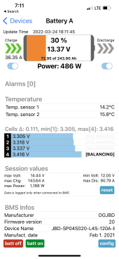
1. on charge start - Battery A had an orange charge state indicator. Q - does anyone know what this means - web search did not find anything relevant? then it changed to blue after a few min. Battery B was fine.
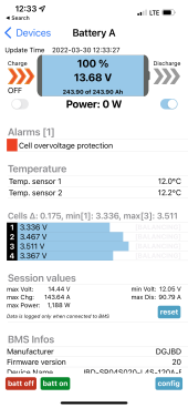
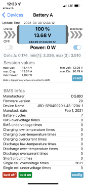
2. on charge complete - Both battery A and B had "single cell overvoltage times" Batt A@ ~1700 times and Batt B@ ~2700 times - but battery A went in to Alarm [1] "cell overvoltage protection".

AND
Battery A's BMS set the capacity back down to 243Ah vs 271Ah (or 280) which is what it should be. I made no config changes here. And the configs match between the batteries. super weird!

Has anyone seen stuff like this?

C
IMG_8273.PNGIMG_8285.PNGIMG_8284.PNG
 
Ok - so i did a standalone charge cycle from around 30% up to 100%
several things happened:
1. on charge start - Battery A had an orange charge state indicator. Q - does anyone know what this means - web search did not find anything relevant? then it changed to blue after a few min. Battery B was fine . . .
The SOC display on the Xiaoxiang iOS app we use with our JBD 200a BMS displays red, orange, or blue depending on SOC. Can't remember exactly, but I believe it transitions from red to orange (or vice versa if discharging) at approx. ~15% SOC. Transitions from orange to blue when charging at approx. ~30% SOC (blue to orange when discharging).
 
Is that a max charge rate of 143 amps? If so, that seems a bit aggressive. Reducing the charge rate would give the cells more time to balance.
 
I don't have enough data to produce a full report but after 4 months of working pretty much every day on this project, I finally just sealed up everything up last week and said if it burns the house down, so be it. I have dual 280aH banks wired in a mirror image, same exact length of cables and connectors and same dual side-by-side JBD 200A BMS. I have dual battery switches with dual same thickness solid copper buss bars feeding from a 2/0 battery cable through dual 200A bussmann fuse bars through dual 350A switches connected into my house 4/0 welding cable inverter feed. I honestly think this BMS must be a prototype version or something. I've looked at my cell data charts via Android and there is no way that these cells have peaked up as high as 4.2V and down as low as 2.5V and danced all over the spectrum like these graphs show. I never put the voltage on the house line for them to do that and there's no reason they would have ever had spikes down to 2.5V. Additionally I have gone through all the custom Android parm settings about 6 times, writing everything down and both of the identical 200A BMS configurations are exactly the same. And no I do not have loose buss bars because I have torqued them 3 times and I can run a 150A microwave for 8 minutes and all the cells measure the same and every buss bar is cool to the touch, so I think it is the BMS and not the installation. This is also proven by one BMS (while switched both banks on long-term in tandem) shows all the individual cell voltages as equal, yet one BMS says I am 35% power and the other says I am at 65% power while both read identical on the cell voltages within 0.02 (.) Also one BMS shows I have 62 ? "time left" and the other shows I have 158 ? "time left" - whatever that means and this is noted while all the cell voltages on both banks have been working in parallel for several days while all cells are showing the same voltage within 0.02 of each other. Other tidbits include that I wired in dual identical coulomb meters (battery monitors) with the shunts wired right before the BMS grounds to the frame so I can double check what the amp meters on the Android panel is showing. Watching the Android panel meter vs the battery monitor will show that if charging option is turned off, the meter on the Android panel will freeze while the battery monitor shows it is actually still discharging like you asked it to, which means the firmware is doing what you ask but the meter on the display stops showing discharge amps when the charge option is shut off. So I am guessing there is some bad firmware going on here or some other extreme oddity is causing the differences of reporting on the BMS Android panels because with the bank running long-term with the two tied in parralel, the voltages of all 8 cells stay very near the same but the BMS is all over the map as far as percentage charge, ???time-left??? and the operation of the meter with discharge/charge off/on is messed with.
Side note, when I switch off the charging option on both BMS panels, again with both banks in parralel, by simply turning on the microwave (150A) caused one of the BMS to automatically turn charging back on its own. So there are too many flaky things with these BMS units to try to set up any kind of scientific lab work or gain too much of an education about the workings of LiFePo4 in my opinion to invest too much time into it other than saying what his presented here is better than nothing at all.

Otherwise, way too much time, unexpected outflow of too much money for all the connectors, cable runs, etc, etc, etc that I am going to let this setup run now without wasting any more of my life on this setup and if something goes or burns out before 10 years, chances are I am going to be gone before they are and especially if I take on another project like this. This one is simply not fun any longer. Also if I cause one cell to last only 5 years instead of 10 because it let it float at 13.8v instead of 13.6v, it's now all so clear that in time and worry, it's cheaper to just buy a new set of batteries if you find their life has been shortened (at least for someone like me in the 12V market, as far as the homeowner with banks after banks of these 280 3.2A - all I can say to you is good luck brother managing these.

P.S. I forgot to note that in the tight quarters where I had my old lead/acid solar controllers mounted, this took a couple of weeks to remove and re-mount almost $300 worth of new solar controllers for my two dissimilar size solar arrays. So short story is this is great for someone who is looking for something to do but if you are aching to get back on the road again, it's one project that can quickly turn into a career rather than a single "winter project". Also note that if I was going to watch the meters and shut off charging when it got above 13.6 and discharge my cells to where they only got "this" high and discharged down to "that" low then I would tow a trailer of lead/acid before I'd spend any more time on this. My cells "go to sleep" anyway when they get to about 13.8V and I know the meters are accurate because while the Android meters for the 2 BMS show "0", the battery monitors show only about 0.05 to 0.1 charging amps when the BMS meters are showing zero. So since nothing trips off any of the BMS cut-off criteria, I assume once they reach this voltage level, they appear not to accept any more amps even if I start the alternator to pump some 14.2V into them. Either it has to be the cells don't take more current when they get to 13.8v (divited by 4) or otherwise and unless there is an entire other program executing in these BMS units that is not documented, they are "quite done" at 13.8V. Incidentally, when I have read of all the people saying that the alternator at 14.2V needs a B2B to charge at 14.4V, I have to wish I was on that influencer payroll. If you've asked me the very largest surprise and revelation of what I've learned with this project, it just how much pure BS is circulating about the way these cells work. Buenos Suerte! YMMV
 
P.S. I hope I am not hijacking your thread. With that I am going to add one more rumor to the rumor mill to join the ranks of batteries must be mounted in a vice, B2B are to be used with no consideration for alternator capacity and performance and that cells must be top balanced in parallel with a power supply. This new rumor will be that these cells can actually see what you write about them online so if you insult them heavily as noted yesterday, this morning you wake up to them having slept well on the 13.6 constant power of your converter while they all read an identical 155:18 "time left" and all cells, including both separate 12v banks in parallel are reading 13.6V @ 3.40 per cell. Where it goes from here I don't know but one thing for certain, I need to put all these meters and monitors away for a while LOL.
 
several things happened
Corbury, I installed a coupe of Heltech BMS 4S 5A Active ballancers (around $20US on ali), actually I installed 2 on each set of 12V group of 4 cells but after a few charges and drains, it doesn't seem like I need a full 10A any longer.
 
Ok - so i did a standalone charge cycle from around 30% up to 100%
several things happened:
1. on charge start - Battery A had an orange charge state indicator. Q - does anyone know what this means - web search did not find anything relevant? then it changed to blue after a few min. Battery B was fine.
2. on charge complete - Both battery A and B had "single cell overvoltage times" Batt A@ ~1700 times and Batt B@ ~2700 times - but battery A went in to Alarm [1] "cell overvoltage protection".

AND
Battery A's BMS set the capacity back down to 243Ah vs 271Ah (or 280) which is what it should be. I made no config changes here. And the configs match between the batteries. super weird!

Has anyone seen stuff like this?

Did you ever figure out the reasons for the troubles?
 
Did anyone ask if the Overkill was set to "balance all the time" or something similar, rather than "balance on charge?" Could it be as simple as that?

I'm no Overkill expert, but what I see is a need for mass simplification, otherwise you may have a setting wrong in your bms app, and to correct for THAT, you are now hanging active balancers all over. Meanwhile the SOC meters are uncalibrated and so forth.

Sometimes, too much access to user-settable options, can be a BAD thing.
 
The colored cell displayed on the Android app shows the individual cell that is the most out of balance both above (red) the other 2 and which cell is the most below (another color and I've forgotten since I don't pay attention to them any longer (maybe white?). I have thought about these cells and I believe the issues with these types of cells is they are all used no matter what the ad says and besides that, the company that sells them must just line up cells, write their voltage next to each cell on a board and sort them in different static voltage groups. Then when your order comes in to the factory, they grab 4 of near the same voltage and send them out as a group and no matter the history or age or other conditions of each cell. This what appears to be going on from looking at the true full-cycle performance of the cells. There's not really any reason for using the JBD or Overkill auto balance, because at a tenth of amp or less, there's no real reason to turn it on.

Adding two Helltechs @ a total of 10A of balance current will allow the drain-down of the batteries at maybe 30A rate or so with no issues but if you do something like run an A/C, microwave or send 120A to the bank long term and come back with a triple digit charge, these used cells don't seem to handle it well enough and the dissimilar aged cells can't stay up with each other during fast-charging and that's regardless of the balancing. I've now decided if high amp loads and high amp charging is the plan, and regardless of adding the Helltech, using these mystery-quality cells is not going to provide close to production quality. Having the Heltech onboard though when you are talking triple digit charge/dischard levels, while it does at least make them usable, as far as a quality solution these are not a good fit. However considering a long term deep cycle discharge, at least a 10A double-Heltech will keep them from being trashed but don't expect a miracle. As far as the internal balance circuit of any 100-250ma BMS, don't even bother turning it on because you may have left the earth before it balances.

Still regarding some of the poorer condition prismatics you will receive, even charging at 80A will cause the BMS to stop allowing charging well before the 4 in series has charged and sometimes even at 85% and lower the charging ticks off. The only way I have found to use one bank that I have is with the cell cut-off voltage at 3.65, then upping the over-voltage release from 3.45 to 3.60. I can't make it go any higher for that matter. What this does for you is that it sets your charge rate on the higher SOC end so there's shorter wait times in the on/off charge cycling. You go from a short burst every 15 minutes up to a short burst every 2-3 minutes, rather than if the overvoltage set on 3.45 which means that the charge can take several days to reach 100% and no matter what amperage is poured into them.

I'd say now after 10 months experience using them to not invest in these unless you can find absolutely without a doubt, new cells that have NEVER been used before and I'm not sure how you are going to do that.
 
Back
Top