diy solar

diy solar

problem with capacity tester?

scott harris

New Member
Joined
Jan 1, 2020
Messages
92
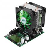
I have one of those Chinese capacity testers with the fan. I have used it in the past to test 60 AH and 100 AH batteries without problems. Now that I am testing 280 AH cells at 18 amps (max I can get it to go) I noticed that the voltage displayed on tester is 0.3 volts less than that measured at the input of the tester. So my test stops when the cell is at 2.8 volts because the tester thinks it is at 2.5 volts.

Is this typical?
 
If you run them near their wattage limit, they can burn up.

18A at low voltage will have a lot of voltage drop. Thick wires and beefy connectors can help, but you're probably going to see at least 0.2V drop. Can compensate simply by discharging to 2.3V or whatever.
The voltage drop is not between the battery and the tester, the voltage at those two points is the same. (I am using 10 guage wire and the length is only one foot. I am using ring terminals on all four ends.) The drop is between the input of the tester and what the tester displays.

I might have had this same problem before and did not notice it because all the previous cells tested higher than rated. These cells did not reach 280 AH, in fact only 275 AH even with a discharge rate of only 0.06C.

I would like to know if anyone else has this same issue with this capacity tester.


Can compensate simply by discharging to 2.3V or whatever.
Good Idea. Thanks
 
I usually mention it, but I failed to this time. The unit itself has internal resistance. If it has a voltage calibration feature, you could possibly get rid of the issue that way.
 
The voltage drop is not between the battery and the tester, the voltage at those two points is the same. (I am using 10 guage wire and the length is only one foot. I am using ring terminals on all four ends.) The drop is between the input of the tester and what the tester displays.

I might have had this same problem before and did not notice it because all the previous cells tested higher than rated. These cells did not reach 280 AH, in fact only 275 AH even with a discharge rate of only 0.06C.

I would like to know if anyone else has this same issue with this capacity tester.


Good Idea. Thanks

I’m having exactly the same issue and interested in any workarounds.

Has anyone figured out how to do the voltage and current calibration on the 150W testers and can that help?

I’ve also read a few places that running close to the maximum 20A is a quick way to burn these out, so what is a ‘safe’ discharge current? 10A? 15A?

Any advice as to how best to test capacity of a 280Ah cell with one of these appreciated.
 
You want to keep them under 90% of the POWER limit.

Start a discharge, note the voltage difference between the tester and a direct measurement of the cell. Lower your discharge termination voltage by the voltage difference.
 
You want to keep them under 90% of the POWER limit.

Start a discharge, note the voltage difference between the tester and a direct measurement of the cell. Lower your discharge termination voltage by the voltage difference.
Gotcha, thanks. So 18A on one of those 20A/150W testers is pretty safe, right?

And then measure the voltage drop between the battery and the tester at than Amperage and lower to discharge termination voltage accordingly, got it.

Even at 0 current I’m getting a voltage mismatch between the cell voltage measured by multimeter and the cell voltage measured by the tester - has anyone figured out how to calibrate one of these things, especially the voltage?
 
I have the 180W model shown below. It also has a voltage difference of 0.42mv between cell actual voltage and that seen at the test terminals. I'm using 14g fine copper with crimped ends. There is a calibration setting but I never played with that as the docs discourage it... Instead, I reset the cutoff to 2.0V which triggers at 2.48V and after the cell settles back up to roughly 2.52-2.55. This is after a constant 20A load test running for 14 hours (doing it on 280AH EVE's.)

I've attached the manual to mine, in case it may be of help.
I just noticed, these guys just came out with one that has logging for PC Serial Port capture... bugger

180W tester.jpg
 

Attachments

  • 180W Cell-Tester Manual.pdf
    80.6 KB · Views: 28
You mean 42mV not 0.42mV which is really low value <1mV. Do you have the link to that model? Thanks.
That manul is the same as the one I have that has smaller heat sink.
 
Gotcha, thanks. So 18A on one of those 20A/150W testers is pretty safe, right?

I think you missed the POWER part.

If you are running 18 amps at 14v you are well over the power limit. Even when it drops down to 12v no?
 
I think you missed the POWER part.

If you are running 18 amps at 14v you are well over the power limit. Even when it drops down to 12v no?
I’m testing single cells. 3.4V, not 14V.

20A would be less than 70W, so no issue from a power/heat perspective.

But if sustained currents of 20A can fry the transistors, that’s a reason to test with lower currents (18A or less) even when the power is well under 150W...
 
I have the 180W model shown below. It also has a voltage difference of 0.42mv between cell actual voltage and that seen at the test terminals. I'm using 14g fine copper with crimped ends. There is a calibration setting but I never played with that as the docs discourage it... Instead, I reset the cutoff to 2.0V which triggers at 2.48V and after the cell settles back up to roughly 2.52-2.55. This is after a constant 20A load test running for 14 hours (doing it on 280AH EVE's.)

I've attached the manual to mine, in case it may be of help.
I just noticed, these guys just came out with one that has logging for PC Serial Port capture... bugger

View attachment 31775

Those are the same docs that came with mine. If by ‘discourage it’ you mean the Note at the end of the Description:

‘(Note: Please don’t calibrate the voltage or current if without standard instruments)’

I’d hardly call that ‘discouraging it.

The real issue is there is no explanation for how to perform calibration other than the one reference to ‘current data reset to zero (0.00A).’

Of course the lack of any instruction is very discouraging - who’d want to risk screwing up their unit bumbling through control menus without any guidance at all.

There are some YouTube videos hinting at how to calibrate a similar-looking unit so I’d hoped someone on the Forum had cracked the code, but looks like we’re all in the same ‘if it ain’t broke, don’t fix it’ (ie: discouraged) boat.

From my understanding, the only difference between my 150W unit and your 180W unit is the size of the heat sink and the fan, so if you are able to sustainably test successfully at 20A, heat sounds more likely to be responsible for folks burning their 150W units out rather than current of 20A.

There is a setting for Max Power and my 150W unit came preset at 180W. Anyone using a 150W unit without adjusting their Power Limit setting to 150W risks frying their transistors from too much heat.

The final Warning is pretty clear on this:

‘5) Be sure to obey the law of conservation of energy, the product of the voltage and the current should be less than 150W.’
 
This guy seems to have figured out how to calibrate one of these (starting around 14 minutes):

You need to go into the setup menu, then apply precisely 10A at precisely 30V from a power supply.

The fact that the calibration occurs at 10A is a further reason to test at 10A since that should deliver an accurate voltage reading at the tester (lower than battery voltage by whatever number of mV is appropriate for 10A through your testing wires).

The advantage of calibrating the current reading and voltage reading at the tester is that once load current is reduced to 0A, the tester should provide an accurate reading of battery voltage.

This video was clear enough that I think I’m ready to be the guinea pig...

Another video I found ran testing near maximum Watt rating and discovered discoloration on the bottom side of the board below the power transistor (beginnings of a burn mark).

Seeing that makes me think you’ll quickly wear out one of these testers running it at near 150W and limiting to below 100W or even 75W is likely to greatly increase lifetime.

The best thing to do if you want to push test current/power to the max, of course, would be to measure temperature under the transistor while in the middle of the test.

I’m just going to stick to 10A when testing individual cells for now.
 
10A at 30V? It exceed the capacity of the tester...I bet the MOSFET will go in flame and smoke!
 
10A at 30V? It exceed the capacity of the tester...I bet the MOSFET will go in flame and smoke!
He didn’t say it clearly. It’s10A at low voltage to calibrate current and 30V at low/no current to calibrate voltage.

The calibration for current and voltage don’t happen together, they are two separate calibration steps...
 
I have one of those Chinese capacity testers with the fan. I have used it in the past to test 60 AH and 100 AH batteries without problems. Now that I am testing 280 AH cells at 18 amps (max I can get it to go) I noticed that the voltage displayed on tester is 0.3 volts less than that measured at the input of the tester. So my test stops when the cell is at 2.8 volts because the tester thinks it is at 2.5 volts.

Is this typical?
Yes, but mine stops at 2.7 volts. I am using 10 Guage copper wiring, if you are using smaller wiring or don't have a perfect connection, that might be the difference. I set mine to stop at 2.4 volts. If checked with a meter immediately, the cells read 2.6 at the terminal, then climb back to 2.7 volts after a minute or so. I set the coarse and fine adjustments to max, and it claims 24 to 23 amps being drawn.
 
My MOSFET blew up when I test just one cell 3.4V at 20A, it shows 20A for seconds then it no longer shows current draw, luckily I have spare MOSFET in stock, the didodes next to the MOSFET alos run very hot and due to height difference between the MOSFET and the diodes, the heatsink does not make contact with the diode so the heat is dissipated on the copper plane instead, it is too hot to touch. i was able to run at 15A for 24 Hours,
 
Last edited:
My MOSFET blew up when I test just one cell 3.4V at 20A, it shows 20A for seconds then it no longer shows current draw, luckily I have spare MOSFET in stock, the didodes next to the MOSFET alosrun very hot and due to height difference between the MOSFET and the diodes, the heatsink does not make contact with the diode so the heat is dissipated on the copper plane instead, it is too hot to touch. i was able to run at 15A for 24 Hours,
I’m limiting my capacity testing to 10A (on a 150W model) precisely because I’m worried higher currents will damage the flimsy design over a >24h test.

Draining a full cell takes twice as long, but 10A also makes the math exceedingly easy...
 
Back
Top