diy solar

diy solar

[Project] Extending EV range by offsetting auxiliary 12v loads using solar

I don't want to replace an ICE vehicle having 300 ~ 400 miles range with a car having 140 miles electric + 130 miles gas range. (220 EV a bit better)
On a trip, that would mean only 2 hours driving from full to empty. And see above abysmal performance with "limp home" ICE mode.
Haha. I have been driving EVs since 2012. I am also 70 years old and have to pee every two hours. That means by the time I get to the restroom, get my pants unzipped, and get some flow, my Tesla has another 150 miles of range. Not a problem for me. I am unfamiliar with the "limp" mode you are referring to. That is another issue unrelated to the kind of vehicle I drive.
:LOL:
 
So just a little update:
I recently received the 1800w DC boost converter I ordered, along with a shunt and some other stuff for my experiments.

Yes, 1800w is pretty much overkill for my needs (only need around 300w, maybe 500w for future improvements). But this little board was tested and recommended by various YouTubers. There are some lower power DC boost converters with a digital display, but from online reviews they are unreliable and don't put out what they claim.
I also ordered another more compact version of this board, the 1200w rated one (has a much lower profile). But didn't receive it yet.
I wanted to have a spare anyways, just in case I mess up something and fry the board.

In short, this board does what it says, but it took me a while to set it up properly, as it only had some POTS for the settings, no display.

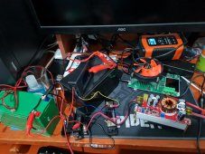
After a night of testing the DC boost, with some batteries and a battery/load tester (now just recharging my batteries) my desk looks like a nightmare :eek:

20211028_055122.jpg
But it was fun! This was also the first time I had connected/used a shunt and monitor. Did some beginners mistakes with it, but it's working nicely.
The only downside to this specific shunt is that shows charging and discharging as just current draw, so you can't really telly how much capacity is left in your battery.
Unfortunately after ordering this cheap shunt, I discovered that JUNTEK also makes a wireless shunt, which would be ideal for me, placing the monitor in sight in the car.
Of course I had to order that too...


Well that's it for now.

My next steps are to test my theory inside the car, just with a battery and the DC boost converter, no solar yet.
I want to see that I can offset the loads from the onboard DC-DC converter with my setup.
 
Last edited:
i admire your tenacity to directly offset energy usage in real-time ?

it seems like you are on track to experimentally evaluating the performance of a solar augmentation thing. thanks for sharing updates
 
I did do some testing not long ago.
I was able to see up to 20A draw, but I suppose that the DC-DC converter was supplying it, not the battery.

Unfortunately my clamp meter doesn't have an "inrush" or peak function, so I couldn't check what the peak draw was on the battery when the car was "started" (only checked after the car was on). But I suppose that the draw should be fairly low, as when starting and EV, it only has to supply power to the HV battery contactors/relays.


Are headways more resilient to hot weather than the prismatic cells?
I don't think they are anything special in regards to lifepo4 (140-170 F seems to be upper limit for one google search). I think "headway" cells excel in being able to safely use large amounts of current. They are only maybe 8-16ah 3.2v cells but are labeled as 200amp continuous. Most prismatic lifepo4 cells are much less, often 1C (ie 20ah would be 20 amps discharge continuous).

I don't have any experience with them but there seems to be some sellers in America selling them for a bit less now. They've always been a more premium price. There are lots of lifepo4 options now compared to just a few years ago.

I'd repeat what others have said as well. Get as much weight out as reasonable.

I am in need of a new battery for my Tesla model 3. I assume there are others, but I found a model 3 12v lifepo4 battery for $439 plus shipping and it looks to me like it may be pretty small. It weighs 11lbs less, which would seem to take a long time to pay off in efficient/$$ calculations. I'd also have to reread how a bms would handle low temp cutoff, after reading about some RVers discussing insulated boxes and heating pads to keep their lifepo4 working in cold temps. You don't want to discharge a lifepo4 below a certain temp.

Then again, the 12v tesla factory battery seems to only last around two years, which I think may be because it gets rather heavy use. The newer ones seem better. The lifepo4 appear 4-6x as costly with not much benefit and maybe not good in cold climates.
My problem in ordering LFPs is shipping (to the Middle East).
I even contacted Amy and she said they currently can't ship here.
Same on Amazon. They don't have shipping for Lithiums to my region.
On Aliexpress I was able to find lots if sellers, but the shipping costs are usually hundreds of dollars for 4 Lifepo4 cells with decent capacity (85ah and up). This makes ordering them pretty much impractical.

Locally there is much of a variety, and what does exist is insanely expensive.

Anyways, my problem is heat, not cold weather (barely see 5° C in winter).

I ordered a 12v 20Ah Lifepo4 as a buffer battery from Aliexpress (for about $95). I will test its capacity. If it's good, I will try a temporary swap with my 12v lead acid, just to see that it's compatible. I think 20Ah is a bit small, so if it works OK I may be tempted to get something larger, like 36Ah.
More than that capacity starts getting expensive with the shipping as I mentioned.
 
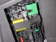
Well, I did some snooping inside my car: I was looking for a proper sized fuse (20-30A) that I could piggy back on, using it to feed back the energy from the DC-DC boost converter.

I was actually lucky, since my car has 2 fuse boxes inside the cabin (and one more in the "engine" bay), and one of them is in the glovebox. I'm planning to place most of the components in the trunk of the car (battery, SCC, shunt, etc...) but the DC-DC converter will be placed in the glovebox.

So, I found a fuse socket that had a 30A fuse, but isn't really in use (it's supposed to be for heated seats, but my car certainly doesn't have heated seats).
I took out the fuse, just to make sure it wasn't in use. Surely enough everything was working fine, no warning lights etc...
Not that I couldn't piggy back on socket that was in use, but I preferred not to.

I was planning to connect a piggy back connection to that fuse socket (with a lower rated fuse, like 20A) and then connect it to my DC-DC boost converter.
But it was a real hassle getting that thing plugged in as it's on the side of the glovebox, and can barely be seen (got my hands all scratched up).

It's the little green 30A fuse (horizontal):
20211020_213935.jpg
Even after connecting it, I had no voltage on it. Turns out I was connecting it the wrong way.
I was hoping it was a switched socket, but turn out it's has permanent power.
Not that bad as I was planning to add a relay anyways, so that the DC-DC boost converter will be powered by the buffer battery only when the car is on.

Having wasted all that time I didn't have a chance to do the testing.

I was also looking for a good ground connection. I found an exposed metal body part next to the fuse box, which looks like I could connect a bolt to it.

So that's it for now. Hopefully next time I will be back with some testing done.
 
Last edited:
Both. Right? I see discharge listed as down to -20 C and charge down to 0 C (via one online pdf). So, where I live both could be a problem for a car parked outside. Not even being able to discharge is less a problem since it should get down to -20C less, but still could be (bit off topic, but my tesla model 3 battery is basically right up against the hood next to the windshield). It doesn't seem like much room to be anything but the air temperature unless the car is being actively used, always stored inside, etc.

The way we all get to be lazy on this is when people have their lifepo4 inside their living space, so this isn't much of a concern.

That said, this scenario of -20C wouldn't occur all that much in most places, and a lead acid/ICE combo may not work then either... I am pretty sure my tesla would be heating its own big battery at those low temps. That may be enough to help.
 
Did some testing tonight:
Connected the DC-DC boost converter to the car (temporary connections) supplied by a small 12v SLA battery.

The setup was a bit sketchy as I am still waiting for some parts ordered (XT60 connectors, 12v relay, crimp connectors, etc...) using fairly high AWG wires I had lying around. Of course my full setup will have properly sized cables and connectors.

I am also waiting for the 12v 20Ah Lifepo4 that I ordered (could take a while).

Anyways, I purposely set the DC-DC to a low voltage of 13v to start with, and slowly ramped up to 14.4v.

I connected a shunt to the output of my DC-DC boost so that I could see what's going on.
The negative was connected to an exposed body part next to the fuse box, and the positive to the 30A socket using a "piggyback" connector.

The car was on, meaning that the onboard DC-DC was also working. At my 13v, no current was flowing. As I ramped up to 14.4v there was some current flowing out of the DC-DC boost!

I did all this slowly, because I knew that my setup was not going to hold alot of current safely.
But it was fun to see around 70 watts being supplied to the car (about 5 amps) !

I think that at exactly 14.4v, the load between my setup and the onboard DC-DC would probably have been equal.
I suppose that if I were to push the voltage up a bit more (say 14.5 or 14.6 at the max), most if not all of the load would be supplied by my setup.
After some of the wires started to get warm, I stopped the testing.

Conclusion: Its possible, and it works!
I still have alot of benchtop testing and tweaking to do, but the theory has been affirmed.

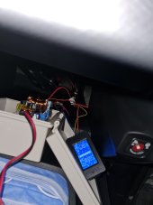
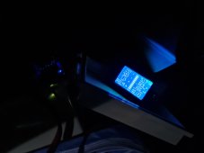
Here are some pics. Sorry for the low quality, it was dark outside and I had to hold some things in place manually...

20211101_200103.jpg

20211101_200122.jpg

When I will have a more robust and proper setup, I will do additional testing/measurements.
One of them is to see how much energy draw on the HV battery goes down when I supply the 12v loads.
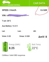
I have an app that connects by OBD2 to my EV, and it displays some interesting information, one of them is current draw on the HV battery.
With minimal loads when the car is on, I usually see between 300-400w.
If I turn on the headlights and the A/C on, this can go up to 2KW!

Here is an example of what it shows during minimal load (marked in red):
Screenshot_20210513-095933_PSA - Power Cruise Control.jpg
 
Last edited:
Did some testing tonight:
Connected the DC-DC boost converter to the car (temporary connections) supplied by a small 12v SLA battery.

The setup was a bit sketchy as I am still waiting for some parts ordered (XT60 connectors, 12v relay, crimp connectors, etc...) using fairly high AWG wires I had lying around. Of course my full setup will have properly sized cables and connectors.

I am also waiting for the 12v 20Ah Lifepo4 that I ordered (could take a while).

Anyways, I purposely set the DC-DC to a low voltage of 13v to start with, and slowly ramped up to 14.4v.
love the procedure
I connected a shunt to the output of my DC-DC boost so that I could see what's going on.
?
The car was on, meaning that the onboard DC-DC was also working. At my 13v, no current was flowing. As I ramped up to 14.4v there was some current flowing out of the DC-DC boost!
?
fun to see around 70 watts being supplied to the car (about 5 amps) !
???
Conclusion: Its possible, and it works!
? good work! with your metering setup it seems very clear that your hardware was supplying energy to the battery! in excess of ten Joules per second!!!!! ⚡
When I will have a more robust and proper setup, I will do additional testing/measurements.
?great work thus far your approach is pretty good from my perspective. good approach to safety and metering and slowly ramping up all great commendable, taking notes for experiments in the future! ?
One of them is to see how much energy draw on the HV battery goes down when I supply the 12v loads.
excited for investigation into this aspect of the system operation!

wonderful work with OBD2 reader! it’s clear you are going to be able to offset a positive non zero amount of energy in a future setup!

Fantastic Work! ☀️??⚡✅?‍♂️
 
Thanks for you kind words and support!
It makes this project more interesting and fun knowing that others take interest in it too!
 
So it has been a while since my last posts.
Fortunately, items I have ordered for this project have started pouring in. The guys at the post office think I'm crazy for all the packages I received lately o_O
Or at least they think I'm building a nuclear bomb... ;)

Anyways, I'm still waiting for the 12v 20Ah Lifepo4 I ordered. It will probably take a while.
Meantime I have started playing with some of the stuff I got.
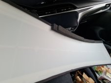
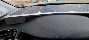
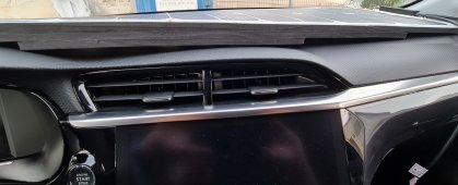
For now I tried to figure out how to mount the solar panel on my dashboard.
I am going for something non-permanent for many reasons. One if them is that I discovered that the passenger side airbag actually opens from the dashboard!
I saw a video of the Euro NCAP crash testing for my EV, looking for the airbag.
Here you can see what I mean:

Screenshot_20211026-075645_YouTube.jpg
So I just want the solar panel to lay on the dashboard, without it moving around much, and not scratching it either. But to allow it to pop-up in case of an emergency (opening of the passenger side airbag).

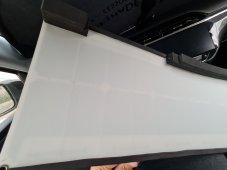
So here comes in handy the adhesive foam I got, in two sizes. I made it adhere to the contours of the dashboard by making multiple levels of the foam where needed.

Here is the outcome:
20211114_151038.jpg
20211114_151043.jpg
20211114_151251.jpg

20211114_151257.jpg


As you can see it still has a bit if twist to it and doesn't lye exactly flat, but I can live with it. The dashboard is very curvy, but at least now the panel has some support. This setup also allows air to flow under.
The foam is only adhesive on one side (the panel side of course), but still it doesn't move much while driving.
I will have to make sure that the cable connections will have enough slack so that in case of the airbag opening, the panel will be pushed easily towards the window, and not obstruct the airbag. It's also pretty light, so I'm not that worried.

That's basically it for now. I have alot of work to do, but since I finally received some important components I can now start mounting and connecting things, to see how they fit and work.

Stay tuned :cool:
 

Attachments

  • Screenshot_20211026-075641_YouTube.jpg
    Screenshot_20211026-075641_YouTube.jpg
    634.4 KB · Views: 0
thanks for the update, cool approach.

good note about airbags.

from the limited views available, your design does look like it has a decent chance of simply being displaced upwards in the event of the airbag deploying. maybe anchor it at far end? nice hack??

even though it’s inside the cabin, it should still generate electricity. some front glass on cars filters out UV.

staying tuned!
Yes, I have tested the output of the panel behind the window. It outputs around 20w (instead of 43w when tested outside).
But that was just a quick test. maybe the angle it has now will be better facing towards the sun.
I need to check again.
I knew that there would be some loss because of UV filtering, but I wasn't expecting that much.
Anyways, I might be adding a panel that will sit on top of the car only when parked (with easy removal) in order to get some more sun juice :cool:

For now I'm just figuring it all out. I will see how it does, and maybe improve it in the future.
What I like about this panel setup is that it will harvest some energy while driving, not only when parked.
 
get those photons! ?☀️

three location options are on my radar,

• inside cabin
• on outside of vehicle
• stowed for stationary deployment

all valid integration strategies imho!?

thanks again!
 
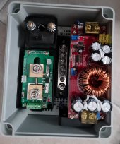
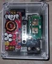
So now I started placing thing inside a project/junction box.
This will go in my glovebox, as I have nice access to the car's fusebox from there, where I will tap into the 12v system.

The items that are in this box are:
  • DC-DC boost converter.
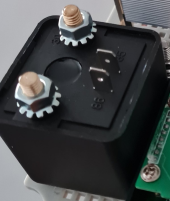
  • 12v automotive relay
  • Ground bus bar
  • Juntek wireless shunt (VAT 1050)
The relay will be turn on by the ignition of the car, and will control the input to the DC-DC converter. Meaning that only when the car is on, it will supply power to the 12v system of the EV.
The reason I'm using a relay and not a permanent connection (from the Lifepo4 buffer battery) is because I don't want to overcharge the existing 12v battery (which is currently SLA, but I have future plans to swap it for Lifepo4 too).
Also, I would rather have the buffer battery charge as much as possible while the car is parked, so I don't want to drain it just for keeping the 12v SLA battery topped-up (self discharge).
If I were to have alot of solar power, I may have chosen otherwise. Maybe when I swap the 12v for Lifepo4, I will change this.
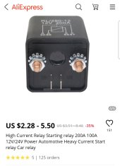
The relay is a pretty massive 200A automotive relay, which is certainly overkill. I am using this one because a 40A one that I order from Aliexpress had pretty thin connectors, and when tested with only 14amps, it heated up alot.

I will be using the Juntek shunt (50A) on the output of the DC-DC boost converter, so that I will be able to see in real-time how much power is being supplied to the 12v system.
I have another 100A Juntek shunt, which I plan to use on the buffer battery side, to monitor the battery. What is nice about these wireless Juntek shunts is that you can use many shunts with the same wireless display. The shunts are addressable, so you can just choose which one to monitor on the display.
I haven't tested this feature yet, but I have seen this online in reviews and so it should work fine.

Yes, I know that all this is overkill for this experiment (and adds up to the total costs) but: 1. I am a data freak 2. Good monitoring will help me understand how efficient and effective my setup is.

As for the DC-DC converter, it will have a permanent connection on the output side to the car's 12v system (always on, not relayed).
This is due to the nature of DC-DC boost converters: If they have no load on them when they are powered up, there will be a high voltage on the output side. This could easily fry my car's 12v system. Therefore there will always be load/connection on the output side, and only the input side will be relayed.
I took the fan from underneath the DC-DC heat sink, and mounted it vertically.
I will be drilling/cutting holes in the box to allow for airflow and heat dissipation.
In this 1800w model of the DC-DC, the fan comes on only when its hot. On a 1200w model I got, the fan is always on, and is not controled by temperature.

There is some parasitic draw from the DC-DC on the output side if it's not powered (I think mainly due to some capacitors and an LED). But it's only a few miliamps, so it's forgivable.
Same goes for the Juntek shunt connected to the output.
But I think it's negligible, and prefer it this way rather than take the risk of damaging the car's 12v system (as explained above).

The bus bar is for connecting all grounds (relay, input and output).

Here are some pics after mounting the components on this nice project box which I got with a matching bottom plate.
This is before wiring, because it will probably get a bit messy after that :rolleyes:
I am also waiting to receive some good tin-plated copper lugs, and a hydraulic crimper so the wiring phase will have to wait.
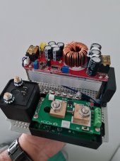
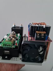
20211116_113923.jpg20211116_113935.jpg20211116_113955.jpg20211116_114206.jpg
 
The relay is a pretty massive 200A automotive relay, which is certainly overkill. I am using this one because a 40A one that I order from Aliexpress had pretty thin connectors, and when tested with only 14amps, it heated up alot.

How much current does the coil draw?
Is it rated for continuous or intermittent duty?

1637073972329.png
 
How much current does the coil draw?
Is it rated for continuous or intermittent duty?

View attachment 72434
It seams to draw ~300ma @ 12v.
I'm not sure about continuous load, the specs on Aliexpress are not so clear.

But it's more than enough for my use which will be around 20 amps
 
300 mA at 12V = 4W
4W x 24 hours = 100 Wh/day

PV panel producing 20W, 5 hours effective sun, 100 Wh/day.

Is this only enabled while driving?
While driving, assume random orientation of panel.
20W output (when oriented ideally) is considerably above 4W loss but with panel swept through 360 degrees orientation and shaded at times, average output may drop as low as 4W, resulting in zero gain. (so only when parked with suitable orientation and relay off would power be gained.)

"Continuous" - I wasn't referring to contact current rating, rather coil rating. Can it be powered continuously, or will it burn up?
Some relays are for intermittent use, like for a starter or winch. Others are enabled the entire time vehicle is operated. A high current relay might have higher current draw, stronger electromagnet.
Compare its current draw to a typical 10A or 30A automotive relay.
It's supposed to be on only while driving, so the current draw doesn't bother me that much, but yes it's a bit high.

You have a very good question about the relay type! I didn't know that there is a difference. From the description it seems you may be correct: this is a starter relay ?

SmartSelect_20211116-192844_Chrome.jpg

Are you saying that if this will be on for a prolonged time (during driving), it will burn the coil?

If so, I have wasted money (again...?)
Darn it, I thought a relay is just a relay. It's a shame they don't emphasize this issue on the product description.

As mentioned, the first automotive relay was pretty crappy. It heated up alot during my short test. But it was a 40amp relay, pretty standard automotive type (probably not the starter type).

Thanks for pointing this out. Do you have any recommendations for my use?
I need a good 12v relay that can handle 20-30 amps continuously. Preferably with a matching socket and wires for easy installation.
 
Back
Top