I have been busy past few days. The positive leads from the solar panels go into a breaker switch then into the respective SCCs. All wires from the roof to the SCCs are the same length by color. All the black negative lines from the roof to SCCs and from SCCs to Bus Bars are equal. The positive feeds to the breaker switch are equal length as are the feeds from the bottom of the breaker to the SCC + connection. The red wires to the breaker and on to the positive bus bar are also equal length. I have wired a bypass switch with resistor to pre charge the capacitors for the SCCs.

The main 12 volt wiring is shown below. The Victron MultiplusII 3000 12 120 calls for 2 1/0 feeds for the positive and Negative leads to the MultiplussII. That coupled with the fact 2 40 Amp SCCs are significantly less expensive than one 60 or 80 amp SSC necessary for 4 210 what solar panels has caused me to make essentially 2 parallel systems that Join at the common Black Covered and Red Covered bus Bars. The smaller gauge red and black wires coming into the respective bus bars from the left connect to the existing 5th Wheel 12 volt bus bars that feed the Distribution panel and take electricity where ever Elkridge wired stuff. I did not change any of that. I did disconnect the shore power feed from the distribution panel breakers and put in a covered 50 amp junction box on the floor behind the distribution panel and connect the heavy black 50 AMP 4 wire AC cable to the AC input of the MultiplusII. I also ran the same type cable from the AC output back to the distribution panel hooked up the exact same way the original shore power was connected.
I am installing 2 310 AMP LiFePO4 batteries. The bottom battery connects to the Red wiring closest to the MultiplusII. I have installed a 150 AMP fuse on each of the battery feeds. Primarily because I am running 150 amp day BMSs on each of the batteries. The feed for each battery goes thru the fuse to the respective cutoff switch and on to the bus bar on the positive side. I have wired a 50 Ohm 100 watt resistor as a bypass across each of the cut off switches to pre charge the capacitors of the Multiplus II. At the red covered busbar the DC positive lines run to the MultiplusII and the positive battery connection from the SCC are connected. In retrospect I probably could have made do with one bypass and charged the MultiplusII capacitors and the SCCs by intially having the breaker between the SCCs and bus bars in the off postition charged the MultiplusII capacitors for 20 seconds or so then turn on the SCC breakers. Resistors and switches are inexpensive and the redundancy appeals to me so there you are.
On the negative side the black 1/0 cable will run from the P- on the respective BMSs on to the shunt and then to the Black Covered bus bar where the negative runs from the MultiplusII and the 2 SCCs join.

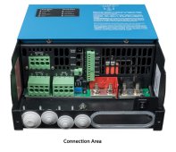
On the inside of the trailer I have mounted the remote control unit for the MultiplusII it is fed by the white RJ45 cable that is visible going into the bottom of the MultiplusII. I was able to mount that controller in the existing power panel cabinet for lack of a better term. Had I planned better I could have also mounted the MT50s for the SCCs there but after locating the MultiplusII controller there was not room. I mounted the MT50s just below that cabinet. The black rj45 cable runs from the MT50 that is on the left as one looks at it and controls the SCC that is on the trailers left side (appears on the right in the above picture. That SCC controls the Solar panels that will be on the left (drivers side) of the 5th wheel. The green RJ45 cable connects the right side MT50 with its associated SCC and solar panels.
I was able to make a compression fixture for my cells which also serves as the mount for the BMS and a handle to pick up the batteries. Yet to be done is attaching silcone heating pads to a 9 x 12 aluminum plate that will mount to the bottom of each battery holder and will thermostatically heat the batteries when temps get to 34 degress F and kick out at 38 or 40 F. I have nearly completed making a 2 tier side mounting apparatus to hold the batteries in the existing battery compartment. I will also run a metal strap from the top piece of plywood in the battery holder to the chassis of the 5th Wheel to prevent the batteries from moving forward under hard breaking. There is no danger of them shifting backwards do to rapid acceleration.
The main 12 volt wiring is shown below. The Victron MultiplusII 3000 12 120 calls for 2 1/0 feeds for the positive and Negative leads to the MultiplussII. That coupled with the fact 2 40 Amp SCCs are significantly less expensive than one 60 or 80 amp SSC necessary for 4 210 what solar panels has caused me to make essentially 2 parallel systems that Join at the common Black Covered and Red Covered bus Bars. The smaller gauge red and black wires coming into the respective bus bars from the left connect to the existing 5th Wheel 12 volt bus bars that feed the Distribution panel and take electricity where ever Elkridge wired stuff. I did not change any of that. I did disconnect the shore power feed from the distribution panel breakers and put in a covered 50 amp junction box on the floor behind the distribution panel and connect the heavy black 50 AMP 4 wire AC cable to the AC input of the MultiplusII. I also ran the same type cable from the AC output back to the distribution panel hooked up the exact same way the original shore power was connected.
I am installing 2 310 AMP LiFePO4 batteries. The bottom battery connects to the Red wiring closest to the MultiplusII. I have installed a 150 AMP fuse on each of the battery feeds. Primarily because I am running 150 amp day BMSs on each of the batteries. The feed for each battery goes thru the fuse to the respective cutoff switch and on to the bus bar on the positive side. I have wired a 50 Ohm 100 watt resistor as a bypass across each of the cut off switches to pre charge the capacitors of the Multiplus II. At the red covered busbar the DC positive lines run to the MultiplusII and the positive battery connection from the SCC are connected. In retrospect I probably could have made do with one bypass and charged the MultiplusII capacitors and the SCCs by intially having the breaker between the SCCs and bus bars in the off postition charged the MultiplusII capacitors for 20 seconds or so then turn on the SCC breakers. Resistors and switches are inexpensive and the redundancy appeals to me so there you are.
On the negative side the black 1/0 cable will run from the P- on the respective BMSs on to the shunt and then to the Black Covered bus bar where the negative runs from the MultiplusII and the 2 SCCs join.
On the inside of the trailer I have mounted the remote control unit for the MultiplusII it is fed by the white RJ45 cable that is visible going into the bottom of the MultiplusII. I was able to mount that controller in the existing power panel cabinet for lack of a better term. Had I planned better I could have also mounted the MT50s for the SCCs there but after locating the MultiplusII controller there was not room. I mounted the MT50s just below that cabinet. The black rj45 cable runs from the MT50 that is on the left as one looks at it and controls the SCC that is on the trailers left side (appears on the right in the above picture. That SCC controls the Solar panels that will be on the left (drivers side) of the 5th wheel. The green RJ45 cable connects the right side MT50 with its associated SCC and solar panels.
I was able to make a compression fixture for my cells which also serves as the mount for the BMS and a handle to pick up the batteries. Yet to be done is attaching silcone heating pads to a 9 x 12 aluminum plate that will mount to the bottom of each battery holder and will thermostatically heat the batteries when temps get to 34 degress F and kick out at 38 or 40 F. I have nearly completed making a 2 tier side mounting apparatus to hold the batteries in the existing battery compartment. I will also run a metal strap from the top piece of plywood in the battery holder to the chassis of the 5th Wheel to prevent the batteries from moving forward under hard breaking. There is no danger of them shifting backwards do to rapid acceleration.
Last edited: