diy solar

diy solar

Proper Gauge For 2000W Renogy Inverter + 200AH 12v Battery?

rcnjstudent

New Member
Joined
May 8, 2022
Messages
12
So I've purchased a Renogy 12V 200AH battery and a Renogy 2000W inverter to use as a mini offgrid system should the power go out at home. This is mainly to power my fridge which uses about 600W running and about 1200W surge at most, but I may have other things (like modem, router, Instant Pot) connected to it at the same time. The inverter seems to come with two 3ft 4AWG inverter cables. I was reading online though that this would only be safe up to 1500W of energy though. Should I go with a different AWG if I wanted to max this out to the full 2000W? Not sure why Renogy would send cables rated for less than what the max output of the inverter is, especially if safety issue. Battery would basically be right next to inverter, so maybe 3 feet max if that. Thanks for your help!
 
Last edited:
So, let's do some math.

If I assume the inverter is 90% efficient, at 2000W output it will draw 2000W/.9= 2222W.

As the battery SOC drops, the voltage starts to go down, requiring a higher current to meet the wattage, Consequently, to calculate the input current I use 12V (the lower end of LiFePO4 voltage range). Therefore the current will be 2222.2W/12V=185.2A

Since you should not run a fuse at its trip point, the fuse for the inverter should be 185.2A x 1.25 = 231.5A. You will have to round this up to 250A.

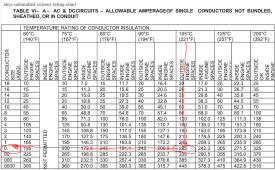
The minimum wire size should support the current of the fuse so we need wire that will support 250A. The wire size for the current will depend on the temperature rating of the insulation. I always use marine-grade 105c wire.

1652044666323.png

From this chart, we see the required gauge is 1/0.

I am not sure why they would ship 4AWG wire with the unit. Even if it has silicone insulation with a 200C rating, it would be too small.
 
So, let's do some math.

If I assume the inverter is 90% efficient, at 2000W output it will draw 2000W/.9= 2222W.

As the battery SOC drops, the voltage starts to go down, requiring a higher current to meet the wattage, Consequently, to calculate the input current I use 12V (the lower end of LiFePO4 voltage range). Therefore the current will be 2222.2W/12V=185.2A

Since you should not run a fuse at its trip point, the fuse for the inverter should be 185.2A x 1.25 = 231.5A. You will have to round this up to 250A.

The minimum wire size should support the current of the fuse so we need wire that will support 250A. The wire size for the current will depend on the temperature rating of the insulation. I always use marine-grade 105c wire.

View attachment 93906

From this chart, we see the required gauge is 1/0.

I am not sure why they would ship 4AWG wire with the unit. Even if it has silicone insulation with a 200C rating, it would be too small.
Thanks for the info, but quick question - in your calculation, it looks like you divided by .9 instead of multiplying by .9. If the assumption is that you could get 90% max stated draw from it, shouldn't it be about 1800W (2000 * .90)? Redoing your calculation above of 1800 / 12V would yield 150A as an output. Not sure if that changes the downstream calculations in a way that would make their supplied gauges acceptable for the unit's real life output?
 
but quick question - in your calculation, it looks like you divided by .9 instead of multiplying by .9. If the assumption is that you could get 90% max stated draw from it
The inverter is only 90% efficient. A 1000W, for example, coming out of the inverter means it needs to draw 1000W / 90% = 1111W from the battery. Another way to look at it is how much wattage will the 90% efficient inverter provide if it is getting 1111W from the battery? 1111W x 90% = 1000W.

So 2000W / 12V / 90% = 185A is the correct calculation since the idea is to calculate how much current must be pulled from the battery for the inverter (with only 90% efficiency) to provide the full 2000W.
Oh ok I understand now, thanks. Does anyone have any recommendations for these types of cables that are from reputable sellers and already have the terminal connectors on them so I don't have to crimp them myself? Since I'm new to this and don't have the proper tools to do this, I'd rather get predone ones that I know were made properly as opposed to doing them myself and possibly having a serious issue afterwards.
 
So, let's do some math.

If I assume the inverter is 90% efficient, at 2000W output it will draw 2000W/.9= 2222W.

As the battery SOC drops, the voltage starts to go down, requiring a higher current to meet the wattage, Consequently, to calculate the input current I use 12V (the lower end of LiFePO4 voltage range). Therefore the current will be 2222.2W/12V=185.2A

Since you should not run a fuse at its trip point, the fuse for the inverter should be 185.2A x 1.25 = 231.5A. You will have to round this up to 250A.

The minimum wire size should support the current of the fuse so we need wire that will support 250A. The wire size for the current will depend on the temperature rating of the insulation. I always use marine-grade 105c wire.

View attachment 93906

From this chart, we see the required gauge is 1/0.

I am not sure why they would ship 4AWG wire with the unit. Even if it has silicone insulation with a 200C rating, it would be too small.
What do you think of these cables from this site, do they have a good reputation? I would get them with the 3/8 terminals on both ends.

 
I have no experience with the company, but they seem like reasonable cables at a reasonable price.
 
105 degrees Celsius is pretty hot. I used the 60 degrees Celsius rating for insulation and went with 4/0.

IMO pre made thick cables are not a good idea. Pretty hard to measure a good length especially if you have not dealt with routing those thick wires.

For a supplier, I used Tecmo welding cable. On a later build, I used a wire rated for where the inverter was located. So indoors, I used THHN from home Depot.
I prefer to be cautious when doing this kind of stuff, rather pay a little more for something more than what my system would be able to generate vs the opposite. That being said, are there any drawbacks (such as additional significant energy usage?) to using a higher degree rated cable other than just paying more?
 
I just used 2/0 Tecmo cable for my camper's inverter-charger installation. Nice stuff, in my opinion, and more flexible than I expected. I'd think 1/0 cable would be pretty easy to work with, but that's just my opinion.
I also bought an inexpensive hydraulic crimper ($47) and the terminal ends, which in my installation were 5/16".
I have to say, I love using my new hydraulic crimper. It was well worth the money, even considering the little bit I expect to use it (maybe a dozen cable ends). Gosh, is it easy to use and get nice crimps!
I hated using the crimper that you hit with a hammer. It never gave me a nice, centered crimp.
 
I hated using the crimper that you hit with a hammer. It never gave me a nice, centered crimp.
The simple trick to using the "hammer crimper" is not to use a hammer. Use a vise. I got really nice crimps putting the crimper in a vise and tightening it as much as possible. A cheater bar helps to get it really tight.
 
The simple trick to using the "hammer crimper" is not to use a hammer. Use a vise. I got really nice crimps putting the crimper in a vise and tightening it as much as possible. A cheater bar helps to get it really tight.
I never got around to buying a vise. 69 years old and I don't have a vise bigger than a jeweler's vise. But then, I don't have a work bench large enough for anything bigger than my jeweler's vise.
 
That being said, are there any drawbacks (such as additional significant energy usage?) to using a thicker cable

I had always wired with 10 AWG and under wire. When I started routing the big wires like 4/0, placement became a challenge to get around tight areas. Also much more critical you buy the correct length or greater the first time around. Pretty pricey to buy 10' more, because you paid for 9' of wire and it was not enough. I buy off wire and cable your way .com and I just found $8.82 per foot.

Here is the 4/0 I bought for the install:

 
Does anyone have any recommendations for these types of cables that are from reputable sellers and already have the terminal connectors on them so I don't have to crimp them myself?

Windy Nation on Amazon used to sell ready-made cables. Probably still do. Good quality welding cable, too.

Buy 2/0 cables.

I would buy 5’ if you need 36”; buy 4’ if you’re super confident that 3’ is enough
 
I buy my cable from https://www.customcableusa.com (used to be geniunedealz.com).

It's not advertised as such, but they've always sent me EPM Marine Master cable. Once I thought I'd try and save some money and went to a local welding supply store. I ended up spending a decent bit more and should have just bought at customcableusa.com instead. The welding cable was more flexy though, so if that's important, the welding cable might be a better deal.

Although this sounds like an advertisement, I'm not affiliated. Just a long-time happy customer.

Edit: One other thing like about the company is they have reasonable prices on terminals. They're not the pretty ancor stuff, but they're heavy and seem to be really good quality for the price. You can also buy just one at a time, which is nice to not have to buy in bulk to get a decent price.
 
Here's a trick I learned about buying wire/cable. Find a local welding supply shop in your area. They will nearly always carry welding cable. That cable is multi-strand and easy to bend. Also, it allows you to "look" at it before you buy it. A bonus: welding shops sell it by the foot. So if you only need 9 feet (for example) you dont have to by 20 on Amazon :) I purchased 4/0 cable from my local welding shop and was able to get the exact amount I needed - and I got to see it before I bought it. Bonus was they sold the ends I needed too!
 
I find local welding supply houses extremely over priced. I can purchase online and usually from either Amazon or eBay, much cheaper even shipped to my door. The local shop unless you have a commercial account and purchase $1000s a year is usually a rip off for the hobby user.
 
Back
Top