diy solar

diy solar

Proposed System for my Sailboat

richwest3

New Member
Joined
Feb 3, 2021
Messages
12
system drawing 1.jpg

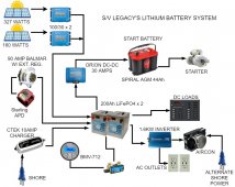
I finally went for it. Batteries and components are on order. Is there anything I should do differently? Here are some details:

The batteries will be made from 280Ah LiFePO4 cells from AliExpress. I'm making two separate batteries, each with its own Daly 150 amp BMS. I did this for redundancy as we are actively cruising in remote places (except during Covid times!) as well as to increase current handling capability.

Solar, alternator and shore charger will all charge a small, 18AH AGM starting battery. Two Victron Orion 30 amp, DC to DC (12-12) converters will charge the LFE batteries. This will limit the output of my Balmar 90 amp alternator to 60 amps. The alternator has a Balmar MC-614 regulator. After the alternator is hot, I seldom get much more than 60 amps anyway so I'm not too concerned about a slight loss of charging amps. Also, it will help reduce wear on the single belt.

Our existing shore charger is small and seldom used, even at the dock. Solar takes care of our electrical needs almost all of the time.

By setting my system up this way, I'm thinking that I'll only have one source charging the LFE bank that I need to worry about. I'm thinking I'll set the Orions up in power-supply mode at a fixed voltage, just slightly lower than a 100% SOC voltage.

This is a simplified drawing and fuses will be added as necessary. So what did I get wrong? What should I do differently? Thanks in advance!

By the way, the drawing is thanks to @Gockleyd for the link to diagrams.net (formerly draw.io). This is an amazing tool. What wasn't obvious at first is that you can just drop images into the scratchpad area and use then as symbols. It's so easy!
 
Solar, alternator and shore charger will all charge a small, 18AH AGM starting battery.
This looks like way too much charge current potential for a small 18AH AGM battery. I would check what your battery specs say about max charge current.

I would think that your Victron 100/30's should charge your LiFePO4's directly. And depending on your usage pattern of your lead acid battery vs your LiFePO4's, maybe a DC-DC from LiFePO4's to charge the 18AH battery?
 
This also may be a good option for one of the MPPT as it would allow you to charge directly from the alternator

Will recently did a review of that unit. You can find it here on the forums.
 
That looks like a great option but the Victron units are pre-existing and I've been using them with my current lead-acid batteries. I am adding the Bluetooth dongles to them though so I can see the data from them on my phone.
 
This looks like way too much charge current potential for a small 18AH AGM battery. I would check what your battery specs say about max charge current.

I would think that your Victron 100/30's should charge your LiFePO4's directly. And depending on your usage pattern of your lead acid battery vs your LiFePO4's, maybe a DC-DC from LiFePO4's to charge the 18AH battery?
Great point and one I hadn't considered. I just assumed that current to the small AGM battery would be limited when the charging sources lower supplied current to maintain the proper charging voltage. A re-think is in order. Thanks.
 
I find diagrams like this more confusing than helpful.

For example, you have arrows running from the solar panels to the AGM batteries then to the DC-DC convertors. But the power wouldn't be running through the batteries. Batteries don't have input sides and output sides, they have positive and negative sides.

If I try to envision wiring this up, you'd have everything north of the DC-DC convertors connected to the same positive and the same negative, and power from the solar panels wouldn't be running through the AGM to the convertors, it would be behind supplied to both in parallel.

An I wrong?
The diagram I posted is a functional block diagram rather than a schematic or a wiring diagram. It serves a different purpose and generally, block diagrams give a quicker, easier overview of a system. A lot of details are omitted in block diagrams; details such as grounds and in this case, fuses. In my diagram, arrows show the direction of current flow.
 
Really like the drawing and would love to know a little more on how you did it. I run an off grid system with almost all the same components except the starter and alternator. Same size inverter, same 280AH Lithium battery, and two sets of panels for a total of 400 watts. By comparison the 400 watts of Panel can go into 450AH of AGM, and there are times it can be a little much. So from my practical experience, 500W of solar panels sounds way to much for a 18AH AGM, I think it will shorten their life. AGMs like to charge slowly especially the last rather inefficient 20% of charge .

It seems more logical that you might direct part of your panel array directly to a the charge controller for the Lithium and a lesser amount for the AGM, if starting is all the AGM it needs to do. We actually use a 30W panel on our boat for maintaining a similar sized starting battery, and have the option of a 30AMP generator adding as necessary. We also carry a backup starting battery (disconnected), as they are small. Our approach is to simplify as much as possible (fewest electronic components), as my experience in boats (CG), is that all components and their operators, are more vulnerable at sea.

On the home Off Grid system I am using a selection switch (Two position) to accomplish selection of PV panel (or both), this located just after the PV array fuses. The net result is to be able to select which PV array to send where in case of any failures.

*Another two position switch is at the Inverter and controller wiring and it allows me to switch the 2000W inverter from the AGM Pile to the Lithium Pile, using either to power the inverter without having the AGM and Lithium batteries land in parallel. (Not applicable in your case).

Hope this is helpful,
Safe boating to you,
kgeorge
 
...So from my practical experience, 500W of solar panels sounds way to much for a 18AH AGM, I think it will shorten their life. AGMs like to charge slowly especially the last rather inefficient 20% of charge .

...Really like the drawing and would love to know a little more on how you did it.

I'm still waiting on the lithium batteries from China so I haven't made any more progress. On the issue of too much current going into the small AGM battery, I think I've found a solution. It seems that spiral AGM batteries have no charging current limit (aside from the ridiculous of course). Optima is one such battery and I verified the max current issue with their customer service.

Since I already have the 18Ah battery, I'll give that a try first. I'm hoping that I can keep the starting battery mostly charged and as such, it won't accept much current. I'm thinking of setting the low end cutout on the DC-DC converters to about the AGM float voltage. Once I get it set up, I'll measure the start battery charge current and report back.

I'm really trying to have just one charging source for the house lithium bank. By doing it this way, I also limit the current my alternator puts out to 60 amps and it solves the issue of an unintentional disconnect killing the alternator or producing a voltage spike.

Instead of switches to reroute power in the event of a dead starting battery or system failure, I'll use a wrench to disconnect and move some wires around. It's not convenient but In almost 50,000 miles of cruising, we've only had a dead battery once (failing AGMs). I have disconnect switches now (high quality marine on/off switches) and I notice they get warm during heavy use. I would like to eliminate that resistance, some wire length, and another possible failure mode.

As for the drawing tool, from my original post: "thanks to @Gockleyd for the link to diagrams.net (formerly draw.io). This is an amazing tool. What wasn't obvious at first is that you can just drop images into the scratchpad area and use then as symbols. It's so easy!"
 
This looks like way too much charge current potential for a small 18AH AGM battery. I would check what your battery specs say about max charge current.

I would think that your Victron 100/30's should charge your LiFePO4's directly. And depending on your usage pattern of your lead acid battery vs your LiFePO4's, maybe a DC-DC from LiFePO4's to charge the 18AH battery?
Hi richwest3,

my main point is: if you keep the LA starter battery in parallel (which is a good idea) why would you need the DC-DC chargers for your LFP? IMHO one would need a DC-DC charger if no LA battery was connected. The LA battery, if large enough, provides the system with a huge capacitor and any voltage spikes from the alternator should be absorbed by it. It protects the alternator and works as a fallback battery once the LFP is full and the BMS disconnects it. The LA starter battery facilitates direct high output alternator charging. With such a large power bank that's what you want!
Other remarks:
  • a starter battery of 18Ah is way too small. You will want to rely on it in emergency situations. I would not go under 80Ah for a small diesel engine. Why would you want to use an AGM battery? A sealed lead acid battery CaAg-type could easily do the job. You can find them easily, they are cheap, they last long (I've changed my last one when it had 10 years) and they can crank out 700A of starting current: 150,- Euro/100Ah.
  • it's good to keep chargers from all sides quite beefy. 10A grid charger seems too small, go for 40A-60A at least (instead of the DCDC chargers)
  • the power of the solar panels is small, try to increase it.
  • Check out if you can fit a large frame alternator which may give you more current like 150A. Yor LFP allows for 280A charge current. With a 150A alternator you should not exceed 70A continuously (you can set Amax in the ext regulator). You would then need 8 hours for a full charge. If you still want more alt charge you would need to install a 24V high output truck alternator. That may be easy in your case if you wire your LFPs in series. You would need a 24V starter battery in that case also.
  • If the LA and the LFP are wired in parallel and won't be separated you can set the LFP charge voltage range to 12,6V-13,4V which gives you 75% of the nominal LFP capacity. The LA starter battery would remain 95% full at 12,6V (floating).
  • You can leave the alternator output at 14,2V absorption and 13,8V float for the LA battery.
 
Last edited:
I'm still waiting on the lithium batteries from China so I haven't made any more progress. On the issue of too much current going into the small AGM battery, I think I've found a solution. It seems that spiral AGM batteries have no charging current limit (aside from the ridiculous of course). Optima is one such battery and I verified the max current issue with their customer service.

Since I already have the 18Ah battery, I'll give that a try first. I'm hoping that I can keep the starting battery mostly charged and as such, it won't accept much current. I'm thinking of setting the low end cutout on the DC-DC converters to about the AGM float voltage. Once I get it set up, I'll measure the start battery charge current and report back.

I'm really trying to have just one charging source for the house lithium bank. By doing it this way, I also limit the current my alternator puts out to 60 amps and it solves the issue of an unintentional disconnect killing the alternator or producing a voltage spike.

Instead of switches to reroute power in the event of a dead starting battery or system failure, I'll use a wrench to disconnect and move some wires around. It's not convenient but In almost 50,000 miles of cruising, we've only had a dead battery once (failing AGMs). I have disconnect switches now (high quality marine on/off switches) and I notice they get warm during heavy use. I would like to eliminate that resistance, some wire length, and another possible failure mode.

As for the drawing tool, from my original post: "thanks to @Gockleyd for the link to diagrams.net (formerly draw.io). This is an amazing tool. What wasn't obvious at first is that you can just drop images into the scratchpad area and use then as symbols. It's so easy!"
18Ah is the starter battery of a lawnmower's gasoline engine! I bet the engine won't even make ONE turn with the power from that battery! How much starting current does that thing crank out?
 
18Ah is the starter battery of a lawnmower's gasoline engine! I bet the engine won't even make ONE turn with the power from that battery! How much starting current does that thing crank out?
The battery is rated at 220 CCA, but has 540 HCA for 5 seconds. I've read where people have started an engine similar to my Yanmar 3YM30 many times on this battery without any charging between starts. I know it's small, but I wanted to save space and weight. I'll let you know how it works out.
 
Hi richwest3,

my main point is: if you keep the LA starter battery in parallel (which is a good idea) why would you need the DC-DC chargers for your LFP? IMHO one would need a DC-DC charger if no LA battery was connected. The LA battery, if large enough, provides the system with a huge capacitor and any voltage spikes from the alternator should be absorbed by it. It protects the alternator and works as a fallback battery once the LFP is full and the BMS disconnects it. The LA starter battery facilitates direct high output alternator charging. With such a large power bank that's what you want!
Other remarks:
  • a starter battery of 18Ah is way too small. You will want to rely on it in emergency situations. I would not go under 80Ah for a small diesel engine. Why would you want to use an AGM battery? A sealed lead acid battery CaAg-type could easily do the job. You can find them easily, they are cheap, they last long (I've changed my last one when it had 10 years) and they can crank out 700A of starting current: 150,- Euro/100Ah.
  • it's good to keep chargers from all sides quite beefy. 10A grid charger seems too small, go for 40A-60A at least (instead of the DCDC chargers)
  • the power of the solar panels is small, try to increase it.
  • Check out if you can fit a large frame alternator which may give you more current like 150A. Yor LFP allows for 280A charge current. With a 150A alternator you should not exceed 70A continuously (you can set Amax in the ext regulator). You would then need 8 hours for a full charge. If you still want more alt charge you would need to install a 24V high output truck alternator. That may be easy in your case if you wire your LFPs in series. You would need a 24V starter battery in that case also.
  • If the LA and the LFP are wired in parallel and won't be separated you can set the LFP charge voltage range to 12,6V-13,4V which gives you 75% of the nominal LFP capacity. The LA starter battery would remain 95% full at 12,6V (floating).
  • You can leave the alternator output at 14,2V absorption and 13,8V float for the LA battery.

Thanks for your very thoughtful reply! I really appreciate it. I thought about paralleling the start battery with the lithium house bank but didn't because I want just one source charging the LFP bank: the DC-DC converters. This will also limit the current draw from the alternator.

The reason I didn't go with a larger alternator is that I don't want to make the change to a serpentine or dual belt system. My current 90 amp alternator is about all a single belt can really handle. I've been using it for almost nine years now to charge a 450Ah flooded lead acid bank and it's been enough. When we motor somewhere, it's usually long enough to get a full charge, even when the sun hasn't been out in a while and the batteries are low.

The almost 500 watts of solar has been great and I have no more room for additional panels. I think one reason is that it's been so good is that the big panel is a rigid Sunpower panel and the amount of power it puts out at even low sun strength or low sun angles is amazing. I often see better than ten amps coming in at 7AM. We're usually topped-up by about 10AM. We have a 12 volt watermaker that draws about 20 amps and we run it about two hours a day. The solar supplies all of that power on mostly sunny days. I think the Victron MPPT chargers are partly responsible for this great performance.

As for the 10 amp shore charger, we seldom plug it in, and when we need it, it's been more than enough. When we're at a slip with power, it can be plugged in 24/7 to provide 240Ah per day to assist the solar panels.

The issue I see with setting a float/bulk to something like 12,6/13,4 is that the LFE batteries would be continuously cycling from 13,4 volts down to 12,6 volts with normal house loads. As the voltage drops between the bulk setting and the float setting, the charging sources would not supply any power. Whereas setting the DC-DC converters to power supply mode would mean that the charging sources would work to supply house loads as they are needed. I also plan to set the charging voltage to something that will be about a 95% SOC, giving me a ton of usable power.

The AC inverter is connected to the LFE batteries to run our new air conditioner - the main reason we're making the change to LFE batteries. We're getting ready (COVID willing) to sail from New Zealand to Indonesia (via Fiji and Australia) and we don't handle the heat well. We're hoping to be able to run the aircon for at least an hour a day during the hottest part of the day. When the compressor is running, it'll draw about 60 amps, but I hope the duty cycle won't be more than 50-60%.

Again, thanks for your insights. I'm still waiting for the batteries but I'll post a conclusion as soon as I can.
 
because I want just one source charging the LFP bank: the DC-DC converters.
Its quite common to have multiple charging sources for LFP banks. Sometimes multiple SCC's, throw in an alternator with a DC-DC and even mix and match with a generator. There isn't a benefit to having a single charge source, probably the opposite.
 
  • Like
Reactions: Mia
View attachment 36045

I finally went for it. Batteries and components are on order. Is there anything I should do differently? Here are some details:

The batteries will be made from 280Ah LiFePO4 cells from AliExpress. I'm making two separate batteries, each with its own Daly 150 amp BMS. I did this for redundancy as we are actively cruising in remote places (except during Covid times!) as well as to increase current handling capability.

Solar, alternator and shore charger will all charge a small, 18AH AGM starting battery. Two Victron Orion 30 amp, DC to DC (12-12) converters will charge the LFE batteries. This will limit the output of my Balmar 90 amp alternator to 60 amps. The alternator has a Balmar MC-614 regulator. After the alternator is hot, I seldom get much more than 60 amps anyway so I'm not too concerned about a slight loss of charging amps. Also, it will help reduce wear on the single belt.

Our existing shore charger is small and seldom used, even at the dock. Solar takes care of our electrical needs almost all of the time.

By setting my system up this way, I'm thinking that I'll only have one source charging the LFE bank that I need to worry about. I'm thinking I'll set the Orions up in power-supply mode at a fixed voltage, just slightly lower than a 100% SOC voltage.

This is a simplified drawing and fuses will be added as necessary. So what did I get wrong? What should I do differently? Thanks in advance!

By the way, the drawing is thanks to @Gockleyd for the link to diagrams.net (formerly draw.io). This is an amazing tool. What wasn't obvious at first is that you can just drop images into the scratchpad area and use then as symbols. It's so easy!

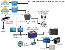
After a shakedown cruise, I had a problem with the Orion Triton VR DC to DC converters getting too hot. I was planning to add fans but that heat has to go somewhere and to get it out of the boat would be too hard. Instead, I revised the system so that the alternator (with Balmar regulator) is now charging the lithium house bank and one of the DC to DC converters is charging the start battery from the house bank.

With the light load of keeping the start battery topped up, the DC to DC converter stays cool. To help protect the stem from a BMS disconnect voltage spike, I installed a Sterling Alternator Protection Device. (I hope the load of the DC to DC converter also helps prevent a voltage spike.) Here's my new system diagram...
system drawing 3.jpg
 
The original design is not good. The later design is much better.
That said, I’d put a DC-DC charger between the alternator source + battery -> lifepo4 cells.
The AGM would act as a good buffer and the victron DC-DC and can deal with the run/off state of the engine.
Also missing here are good controls for charge vs discharge. The BMS I use (SBMS0) allows for this, thus my personal preference.

I have yet to really dig into a sailing system, but I plan to for sure.
 
Back
Top