diy solar

diy solar

Pros/Cons Using Inverter with MPPT Charge Controller

Mitch212

New Member
Joined
Apr 7, 2023
Messages
1
Location
St Johns, FL
One of the basic "kits" being suggested (from various sources) is an MPPT solar charge controller connected to a battery with an inverter also connected to the battery. If the charge controller is attempting to charge the battery with a certain amount of current while the inverter is also consuming various amounts of current (as its load increases or decreases), doesn't that mislead the charge controller as to how much current is actually charging the battery? What are the pros and cons of a simple system like this versus an all-in-one system? It seems the all-in-one systems are more complex and can control how much current is going to charge the battery versus how much current is going to the inverter.
 
One of the basic "kits" being suggested (from various sources) is an MPPT solar charge controller connected to a battery with an inverter also connected to the battery. If the charge controller is attempting to charge the battery with a certain amount of current while the inverter is also consuming various amounts of current (as its load increases or decreases), doesn't that mislead the charge controller as to how much current is actually charging the battery?

Yes, but that really only matters when trying to determine current a full charge criteria.

What are the pros and cons of a simple system like this versus an all-in-one system? It seems the all-in-one systems are more complex and can control how much current is going to charge the battery versus how much current is going to the inverter.

IMHO, I think your idea of the sophistication of the AiO units is a bit unrealistic. They aren't that smart... in fact most of their charge profiles are outright stupid unless you're dealing with BMS communication, and the difference in current is completely meaningless as you can't program a meaningful charge termination criteria into most of them.

Additionally, ALL battery voltage readings of AiO units are wrong. The voltage is influenced by the charge or load to/from the batteries meaning it always reads high on charge and always reads low on discharge as few if any have separate sensing circuit or the option for an external shunt.

Victron systems can have a VE.Smart network where a smartshunt or BMV-712 feeds voltage, current and temperature data to the MPPT for tail current giving the MPPT specific data to determine end of absorption.

In a GX Victron system, the GX control unit can distribute, voltage, current and temperature data to all connected devices including inverters.
 
As a general rule of thumb, the AiO units mostly (but not all) occupy the bottom rungs of the quality ladder. Tier-1 brands, like Midnight, MorningStar, Outback, Schneider, and Victron at the top rungs focus mostly on components.

You get what you pay for. Some of the AiOs are dirt-cheap because of sloppy, low-budget design, construction with marginally acceptable component pieces, and some with recycled parts unsoldered from scrap PCB boards.
 
A simple example:
Take a solar controller producing 100A charge, a 4000W Inverter/Charger and 1 100AH battery.
The SCC & Inverter are attached to 1 side of a Shunt, the other to the battery pack.
The SCC is producing 100A, the inverter is using 10A to power loads and so 90A is going to Batt.
Then you turn on a coffee maker that uses 50A, now the inverter will take 60A from the incoming power and the other 40A goes to the battery.
The coffee maker finishes, the inverter returns to 10A draw and 90A goes back to batteries. The Shunt registers the different amounts going to/from the battery. The incoming power source (SCC or Charger) is irrelevant as it just sees it as incoming power.

As a battery reaches full the voltage reaches a point at which the amps taken decrease's due to increasing resistance. The SCC is usually programed to change into Float Mode which trickles down till the threshold is reached and the battery is full. While the solar controller is in float mode, it can also increase the amount of power supplied IF there is a demand from the inverter. It can increase to the max capacity available (so it depends on time of day & production capacity). Again using the coffee maker example, if Batts are 100% full and you start the coffee maker & if Float can provide 50A extra it will, if it can only provide 30A then the balance 20A is pulled from the battery. After the maker is done, the float Amps can stay higher to replace what was taken from the batts and wind down amps as it completes.

Component Systems while slightly more complicated can be more efficient and further tailored to particular use cases. A good example of such is a part-time cottage/cabin where you want batteries maintained all the time but don't need a running inverter when not in use.

Below is a basic/typical component based system layout.
Hope it helps, Good Luck.
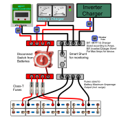

Parallel System-setup PNG.png
 
Back
Top