WYtreasure
It's not happy hour, I'm just like this.
Posts read. Lots of great stuff there. Still gigglin tho. You're bout home aren't you?
You have NO idea how true that is out here... ?The beatings will continue until morale improves.
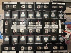
Still need to account for the BMS wire routing, but they work pretty good and makes things a bit safer.

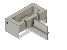
What holds them(cells) together at the bottom?Adjusted the holders to allow for wire routing and finished printing up enough for my first 48v bank. Can also add wires for an active balancer if I decided too later.
I was also thinking of adding in a 1/4 hole through the holders (on the long ends) so that I could run a 1/4" all-thread rod through the entire length just to make it a bit more solid. It would be entirely enclosed by the plastic to no chance of it being exposed.
Took a bit more filament then I had planned, so I need to optimize my infill and support structures when printing....
Currently nothing. I was going to print out some cell holders at the bottom as well, but the battery bank is too large and heavy to move as a single unit anyway. I dont see them shifting any to worry about.What holds them(cells) together at the bottom?
looks great, good work. thank you for sharing this approach.Adjusted the holders to allow for wire routing and finished printing up enough for my first 48v bank. Can also add wires for an active balancer if I decided too later.
I was also thinking of adding in a 1/4 hole through the holders (on the long ends) so that I could run a 1/4" all-thread rod through the entire length just to make it a bit more solid. It would be entirely enclosed by the plastic to no chance of it being exposed.
Took a bit more filament then I had planned, so I need to optimize my infill and support structures when printing....
View attachment 97025
Oh...so not an RV type application.Currently nothing. I was going to print out some cell holders at the bottom as well, but the battery bank is too large and heavy to move as a single unit anyway. I dont see them shifting any to worry about.
Roy
No, this is a static solar build.Oh...so not an RV type application.
may i ask, what level of infill did you use? printer? slicer? PLA material? sorry if asking redundant that has already been shared
Are you going to do anything to prevent batteries from swelling?No, this is a static solar build.
No. I have accounted for the documented spec on swelling (0.5 mm) and have made sure the cells were spaced enough apart. The fixtures are just there to prevent stress on the terminals (in case of swelling) and for safety.Are you going to do anything to prevent batteries from swelling?
So how do you do that?No. I have accounted for the documented spec on swelling (0.5 mm) and have made sure the cells were spaced enough apart. The fixtures are just there to prevent stress on the terminals (in case of swelling) and for safety.
How do I space them apart? I use the terminal adapters that I designed and 3D printed. They provide about 2.5mm of spacing between each cell, while still holding two cells together so they don't move.So how do you do that?

(2.5 mm) > (1mm = (0.5mm * 2)) so no expectation of cell wall contacting each other.How do I space them apart? I use the terminal adapters that I designed and 3D printed. They provide about 2.5mm of spacing between each cell, while still holding two cells together so they don't move.
I have also just added a 1/4 hole through the side so that I can then fix all the cells together so they don't separate. I'll use a 1/4 all thread rod through the length of the battery bank. This is NOT used for compression, just to fix them in place for terminal stress relief.
View attachment 97132


