diy solar

diy solar

PV string with inconsistent power output in low light

michaelvh

New Member
Joined
Nov 29, 2022
Messages
2
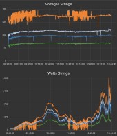
I have started monitoring 4 separate strings on 2 Fronius inverters. The system gives no errors and works but one out of 4 strings is behaving strange on low power. It is a 7kW string and this only happens below 350watts of output power, so in lower light, dawn dusk or cloudy overcast.

That string drops power intermittently and i see voltage fluctuations from 520V to 680V, well within spec of the inverter but something is off. This never happens at higher power levels, where is is most of the time.

I switched one inverter for the other and it shows the same behaviour. Cabling looks fine, anyone can advice on how to troubleshoot this ?
Regards
Screenshot 2022-11-28 at 13.43.06.png
 
All panels have shunt resistance. A typical 300 watt panel will have a couple hundred ohms for shunt resistance, but it can vary from less than 50 ohms to over 1000 ohms depending on quality of panel. Cells in a given panel are sorted for similar shunt resistance but different panels may have different net shunt resistance. Higher shunt resistance panels are generally higher quality panels and when you see a given model family have different power output grades it usually correlates to worse panel shunt resistance to lower power rated panels in the model family.

The shunt resistance typically starts to become significant at less than 200 watts/m2 of illumination on panel. At some illumination point the illumination current is totally consumed by shunt resistance leaving nothing for external load at a given panel loading voltage.

This sometimes causes startup problems for charge controller, particularly in morning. Charge controller detects high enough panel voltage when illumination current exceeds shunt resistance current causing an immediate rise to Voc, but there may not yet be enough illumination to support any significant charge controller current loading causing an immediate panel voltage dropout when an external current draw is attempted.
 
Last edited:
All panels have shunt resistance. A typical 300 watt panel will have a couple hundred ohms for shunt resistance, but it can vary from less than 50 ohms to over 1000 ohms depending on quality of panel. Cells in a given panel are sorted for similar shunt resistance but different panels may have different net shunt resistance. Higher shunt resistance panels are generally higher quality panels and when you see a given model family have different power output grades it usually correlates to worse panel shunt resistance to lower power rated panels in the model family.

The shunt resistance typically starts to become significant at less than 200 watts/m2 of illumination on panel. At some illumination point the illumination current is totally consumed by shunt resistance leaving nothing for external load at a given panel loading voltage.

This sometimes causes startup problems for charge controller, particularly in morning. Charge controller detects high enough panel voltage when illumination current exceeds shunt resistance current causing an immediate rise to Voc, but there may not yet be enough illumination to support any significant charge controller current loading causing an immediate panel voltage dropout when an external current draw is attempted.
Thank you that is a very clear explanation. Is it so that a string consisting of more panels is more likely to show this behaviour compared to a string with a lower amount of panels? (I am thinking adding up the resistances)
In this case, the orange string consists of 18 panels, and shows this behaviour. The other 3 strings consist respectively of 12, 10, and 7 of the same panels (same manufacturer and model, same batch) and they are stable in low light. Would it then make sense to split the large string up in 2x9 panels, if this is withing spec of the inverter?
 
A series string of panels will likely have panels with some variation in the amount of shunt leakage resistance. At low illumination, the panel with lowest shunt resistance will dropout first causing bypass diodes to carry the remaining current from the rest of series array panels and a step drop in Vmp voltage seen by charge controller. It is similar to a panel being shaded but shows up at low illumination level on panels.
 
Back
Top