diy solar

diy solar

Pv wire size for 130ft run at 185v / 25amps?

Dieharddan

New Member
Joined
Jul 12, 2022
Messages
18
Hello, I was hoping someone can confirm If an 8awg wire would be ok for my inverter to panels combiner box.

The run would be 130ft
Im using a sigineer M3048BP 48v inverter
15 panels at 185v 25amps

The sigineer manual states the terminal size is 8awg, but 6awg would go on but would be a pretty tight fit
 
Based on a voltage drop calculator you would have under a 3% voltage drop with 8AWG wire so that should work just fine.

 
Cool, do you know what the voltage drop limit would be safety wise? Or is there no limit?
 
Cool, do you know what the voltage drop limit would be safety wise? Or is there no limit?
Recommendation is generally less than 5%, less is better. Essentially half of one panel is going to be used up due to voltage drop at 3%.

Personally I would go for #6 and transition to #8 at the SCC if wiring space is tight.
 
Recommendation is generally less than 5%, less is better. Essentially half of one panel is going to be used up due to voltage drop at 3%.

Personally I would go for #6 and transition to #8 at the SCC if wiring space is tight.
Thats a good idea, maybe i will go that route
 
do you know what the voltage drop limit would be safety wise? Or is there no limit?
For PV wires there is no safety issue related to some voltage drop. It's just a little less voltage making it to the charge controller. Obviously you want to minimize voltage drop. The general guideline is keeping it under 3% for critical loads and under 10% for non-critical loads.

Going with 6AWG gives you back less than 2V over using 8AWG. Doesn't seem worth the extra expense or effort.

It might actually be cheaper do add 1 more panel than buy thicker wire.
 
This is a calculator I like to use a lot:

Basic URL to calculator:


Example with 8 AWG:


NEVERMIND: rmaddy already posted the same calculator above!
 
Thanks for the responses, im going to go with the 8awg all the way through. I was planning on using 2awg between my sok 48v battery and 3000w inverter, does that sound ok
 
Thanks for the responses, im going to go with the 8awg all the way through. I was planning on using 2awg between my sok 48v battery and 3000w inverter, does that sound ok

EDIT - DISREGARD THIS BELOW, later was reminded by rmaddy this is 48v (not 12v), I knew that but forgot:

2 AWG or do you mean 2/0 (aught - 00) wire on the inverter? 2 AWG might be fine for a charge controller but not a 3000w inverter, more along the lines of 4/0 (aught - 0000) for a 3000w inverter. There are good calculators to help figure out cable gauge with length taken into account.
 
Last edited:
2 AWG or do you mean 2/0 (aught - 00) wire on the inverter? 2 AWG might be fine for a charge controller but not a 3000w inverter, maybe 4/0 (aught - 0000) for a 3000w inverter. There are good calculators to help figure out cable gauge with length taken into account.
It's 3000W on a 48V battery. That's only 75A max from the batteries. 4AWG would be enough. 2AWG is great. 2/0AWG would be overkill. 4/0AWG would be appropriate for a 3000W inverter on a 12V battery.
 
It's 3000W on a 48V battery. That's only 75A max from the batteries. 4AWG would be enough. 2AWG is great. 2/0AWG would be overkill. 4/0AWG would be appropriate for a 3000W inverter on a 12V battery.

Sorry I spaced off the voltage... I remember that now from reading the first part of this thread yesterday, but for some reason today I thought this thread was a 12v one I was reading on another thread...

You are correct, thanks for correcting...
 
After I've sized the wired properly for ampacity my technique for analyzing voltage drop for long home runs is to compare the cost of the next size larger wire to the gained kWh production. For me it's hard to justify 100's of extra dollars to go from a 4.5% to a 3.5% voltage drop. You're just not getting much back for your investment.

Also keep in mind that a 5% voltage drop on 1kw of PV isn't 50 watts of losses because that 1KW rarely puts out more than 800 watts and then only for a few hours a day.
 
My solar array is further than I had planned...I may be 150' from the furthest array to the inverters.
I bought a bunch of #10 wire, and I'm curious if it's worth buying #8 wire instead.
Am I running this calculation correctly?
Would I be foolish to use #10 wire in this situation?
Am I missing something?


I have 4 PV inputs on 2 LV6548 inverters.
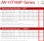
8x395W (49.03VOC/40.73Vmp 9.7A Imp) panels > 4S-2P = 196.12V@19.4A per input (32 panels)
https://www.calculator.net/voltage-...nceunit=feet&amperes=19.4&x=65&y=20&ctype=nec
Voltage drop: 6.92
Voltage drop percentage: 3.53%
Voltage at the end: 189.08
 

Attachments

  • ScreenClip.png
    ScreenClip.png
    294.6 KB · Views: 2
My solar array is further than I had planned...I may be 150' from the furthest array to the inverters.
I bought a bunch of #10 wire, and I'm curious if it's worth buying #8 wire instead.
Am I running this calculation correctly?
Would I be foolish to use #10 wire in this situation?
Am I missing something?


I have 4 PV inputs on 2 LV6548 inverters.
8x395W (49.03VOC/40.73Vmp 9.7A Imp) panels > 4S-2P = 196.12V@19.4A per input (32 panels)
https://www.calculator.net/voltage-...nceunit=feet&amperes=19.4&x=65&y=20&ctype=nec
Voltage drop: 6.92
Voltage drop percentage: 3.53%
Voltage at the end: 189.08

NEC recommends 3-5% for voltage drop as a performance recommendation, once you add in other things into the connection you might wind up being slightly higher.

I personally would go for the 8 AWG if it is financially possible (that's what I spec'd out for mine)... But technically it seems your 3.53% is within acceptable.. I always prefer to go a gauge larger than I may need though, but that's just me.


Ref #1:

Ref #2:
 
.My solar array is further than I had planned...I may be 150' from the furthest array to the inverters.
I bought a bunch of #10 wire, and I'm curious if it's worth buying #8 wire instead.
Am I running this calculation correctly?
Would I be foolish to use #10 wire in this situation?
Am I missing something?
NEC states 690.8 say to size the wire for 125% of Isc = 10.31 x 2 X 1.25 = 25.8 amps so #10 clears that test.

Now do the voltage drop math with the NOCT conditions and see what you think. Your array will only spend a few minutes a year at STC. The rest of the year it will be at NOCT and then only for a few hours a day. I'd be totally ok with the #10 I already had. Just my 2 cents.
 
The calculator requires some sort of conduit. What about NO conduit, open air that is. I wonder if there is a calculator for that or is there a simple answer, or doesn’t it matter for this application?
 
The calculator requires some sort of conduit. What about NO conduit, open air that is. I wonder if there is a calculator for that or is there a simple answer, or doesn’t it matter for this application?
Open air conductors require no derating. Heck, the power company runs #10 open air on 60A drops!
However, if run along a roof, or solar exposed surface, that changes…
 
Thank you all very much! I should have included it's a ground mount in conduit in NE TX.
Due to financial considerations, we decided to punt on the main house goal and build a smaller place a little further back on the property.
Your feedback has been very helpful. Next step...ground mount!
 
Back
Top