diy solar

diy solar

pv wiring cable lenght

adelsolarpinas

New Member
Joined
Apr 12, 2021
Messages
11
hello everyone?
im new here from the Philippines and im building my 1st DIY solar project..

i just want to ask which should i follow.. same equal lenght or not equal so that i dont need to worry about hiding the excess wire ?

what will happen if one pv cable is short? my connection is SERIES..

thanks in advance for the replies ?


EF3AC49E-E91B-4405-8104-18F3E12CC95E.jpeg4F3B6B24-8A0F-4BB4-BBAD-4C113D53150D.jpeg
 
No need for equal length. But you should ground your negative line so you don’t have your panel voltage floating. If you have really long or undersized cable, run it to ground at both ends.
 
Hello, Adel.

You should (of course) cut the longer cable. But your diagram shows something terrible - an Inverter alone, with no batteries in between.

The Inverter wants to receive constant input "DC" voltage at all times, in order to generate output AC power for AC devices. Depending on clouds, your solar panels will have somewhat variable output power - and even slightly variable output Voltage - through the day. You need to add two more things:

1. A set of batteries (a "battery Bank").
2. A "Solar Charge Controller" which tries to keep the battery banked charged properly from the Solar Panels.

Then, the battery bank smooths everything out for the "Inverter". There are many devices which include the "Solar Charge Controller" and the "Inverter" together, Victron makes some very good ones. But you need a battery bank in all cases (with either one "device" or two.)
I assumed it was an over simplified grid-tie schematic.
 
Hello, Adel.

You should (of course) cut the longer cable. But your diagram shows something terrible - an Inverter alone, with no batteries in between.

The Inverter wants to receive constant input "DC" voltage at all times, in order to generate output AC power for AC devices. Depending on clouds, your solar panels will have somewhat variable output power - and even slightly variable output Voltage - through the day. You need to add two more things:

1. A set of batteries (a "battery Bank").
2. A "Solar Charge Controller" which tries to keep the battery banked charged properly from the Solar Panels.

Then, the battery bank smooths everything out for the "Inverter". There are many devices which include the "Solar Charge Controller" and the "Inverter" together, Victron makes some very good ones. But you need a battery bank in all cases (with either one "device" or two.)
thank you for the reply sir ? it is a simple drawing only

what i have right now is a hybrid 5.5kw inverter (china made) i dont have batteries yet.. i still need a lot of work to do.. i will migrate all my load from my old big panel box to a micro panel box

i just tested it w/ 4x 455w panels for a month w/ selected load to see if the inverter works ? (i have 6x455 now)

will post final photo of my project soon.. still need to buy a bigger db box for additional micro breakers, SPD, sinopoly timer and more... ?
 

Attachments

  • 28920630-52D6-4151-A160-8643231F6295.jpeg
    28920630-52D6-4151-A160-8643231F6295.jpeg
    129.6 KB · Views: 11
  • D39A55B5-3610-454D-ABD9-76F9D50B3D10.jpeg
    D39A55B5-3610-454D-ABD9-76F9D50B3D10.jpeg
    121.5 KB · Views: 10
  • 33B70DE1-E70D-46EF-8A61-708FD8811368.jpeg
    33B70DE1-E70D-46EF-8A61-708FD8811368.jpeg
    153.2 KB · Views: 8
  • C90FF3E7-7BFF-4ABA-BC64-30A4A31F7079.jpeg
    C90FF3E7-7BFF-4ABA-BC64-30A4A31F7079.jpeg
    175.3 KB · Views: 9
  • 8E4659F0-F6FF-46A3-88B9-9CBD68182512.jpeg
    8E4659F0-F6FF-46A3-88B9-9CBD68182512.jpeg
    109.3 KB · Views: 8
  • C338AE73-90DD-4475-9BFC-22EE003E16D7.jpeg
    C338AE73-90DD-4475-9BFC-22EE003E16D7.jpeg
    145.1 KB · Views: 9
  • 972A91D5-F27A-4EB8-BB2D-520E4F797BB6.jpeg
    972A91D5-F27A-4EB8-BB2D-520E4F797BB6.jpeg
    90.4 KB · Views: 11
How long is the longest cable run ?
3-4 meters i think.. my actual project is the same as my photo.. the negative line is longer coz its near the inverter while the postive line is farther
No need for equal length. But you should ground your negative line so you don’t have your panel voltage floating. If you have really long or undersized cable, run it to ground at both ends.
thank you for the reply ? the inverter has a grounding line

do i need to have a separate grounding line for my pv panels? thanks again ?
No need for equal length. But you should ground your negative line so you don’t have your panel voltage floating. If you have really long or undersized cable, run it to ground at both ends.
 
Grounding your panels is a good practice. If you have 6 panels in series for a working voltage of 150v (just for round numbers) then if you size your wires for a 3% loss, your panels will be at 4.5 volts. That won’t really lead to a shock hazard but could cause stray current to go where it shouldn’t.
 
Grounding your panels is a good practice. If you have 6 panels in series for a working voltage of 150v (just for round numbers) then if you size your wires for a 3% loss, your panels will be at 4.5 volts. That won’t really lead to a shock hazard but could cause stray current to go where it shouldn’t.
thank u sir :)
 
No need for equal length. But you should ground your negative line so you don’t have your panel voltage floating. If you have really long or undersized cable, run it to ground at both ends.

I would ground the frames. That way, if there is a crack or electrical leakage carrying current from PV to frame, the frame doesn't carry a lethal voltage of several hundred volts. I run a wire from inverter chassis to all panel frames, and have a ground rod at the inverter or electrical panel.

I would NOT ground the negative wire. Not unless inverter (or charge controller) instructions say to do so. All I have ever seen say not to.
thank u ?

it got me confused grounding the "negative line" ?

so i searched youtube.. and found grounding each panel frames ?
 
thank u ?

it got me confused grounding the "negative line" ?

so i searched youtube.. and found grounding each panel frames ?
Here is a very long post, in which I will try to present a bit information about electrical Code "standards", and then show your high-powered panel arrangement to be similar ("analogous") to code requirements for a separate safety ground wire in all 120v/240v electrical service wiring within buildings.
- - -
'Grounding' refers to the Green or Bare safety wire. "Grounded", in Alternating-Current terminology refers to the current-carrying Neutral, and it is a word which I try to never, ever use in describing an AC circuit white wire. In order to prevent the almost inevitable confusion, I try to always describe that wire as the "Current Carrying Neutral" first, and as the "Neutral" afterwards (and always capitalized).

DC Battery "Grounding Wires", and an RV frame, and the bus for Green/Bare "Grounding Wires" should always be interconnected. When a Trailer or RV is plugged into a Grid-Based Service outlet, the green wire leading to the outlet is joined with both a genuine grounding rod and with the current carrying neutral, and with the Utility-provided current-carrying Neutral. But this happens way back at the primary Service panel, where the Utility is connected.

"Current carrying Neutral" should never, ever be interconnected with "Grounding Wires" (the safety and battery grounding wires) before reaching a panel with a true grounding rod. Each panel frame should have safety grounding. As member 'LB3' described in 
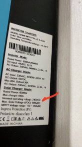
this post (just above), you have "PV+" carrying high Voltage AND high current, and "PV -" at nearly zero Voltage -- but extremely high current. Your "PV -" wire is sort of like the current carrying Neutral in 120/240-VAC wiring, and I agree with LB3 -- with high current and considerable voltage drop along the "PV -" wire, your configuration really SHOULD have a true safety grounding wire into the panels. (A separate connection which normally carries no current at all).

In a common residential arrangement, the PV+ and PV- wires are enclosed in EMT conduit (labeled as high Voltage DC), with the conduit serving as 'safety grounding', providing a genuine safety "Grounding Wire" and being analogous to modern 120/240-VAC wiring practice.

(In the old days, 120/240-VAC was wired without separate bare/green safety wires. All of the resulting fires caused that practice to be discontinued in modern electric codes.)

Within your controller, "PV -" , "Battery -", and your 230-VAC connection share a bus, using the 230-VAC Safety Grounding wire. (Not the white wire!) as the final drain. But with Voltage drop along your PV wires, and high current contained within them, I recommend that you wire between your Solar COntroller and your Panels in a way which is "analogous" to 3-wire 120-VAC: With a separate "safety grounding" connection for the panel frames (through conduit, or wired explicitly separate). It will only carry significant current when something really bad happens - and that is the case for which I recommend that you put it in there. (Lightning Strike, Short Circuit, etc.)
 
Back
Top