diy solar

diy solar

QUCC relay BMS : troubles

cynus

New Member
Joined
Mar 30, 2021
Messages
20
Hello

I have 3 lifepo4 48v batteries and then 3 QUCC relay BMS.
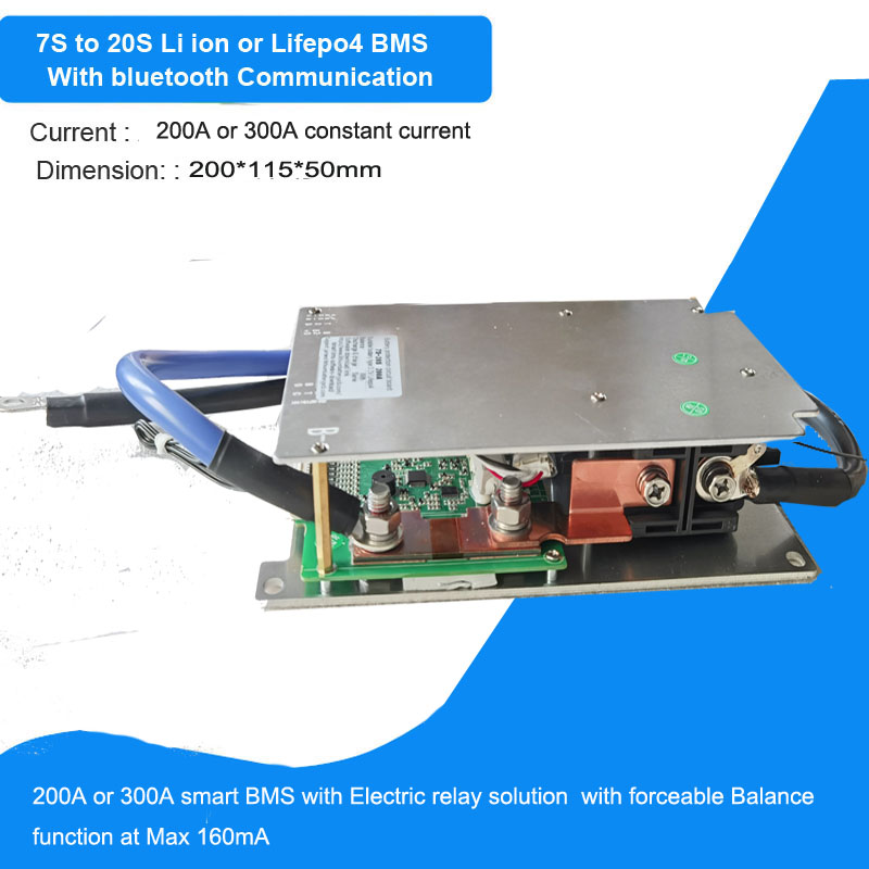

When charging and when a cell go upper than 3.65v the BMS opens the relay. That is OK. The app tells the protection in on. The charge button is off. Good too !
When the cells go back to an acceptable voltage, below release voltage, the app tells the protection is off, the charge button is on. OK. BUT the relay stays opened ! It does not close. It only closes when I reboot the BMS or when the charger send current (at least 20A I think).
So if the BMS disconnects the battery and then the charger stops the charge (because battery is full or sun disappeared) the battery will stay disconnected all night long even if it is quite full ! I will be connected only the next day when sun will make the charger deliver current again.
So of course this BMS is impossible to use in such circumstances with solar systems.
QUCC was no help at all. They just asked me to use standard lifepo4 parameters (what I did).

Am I the only on in this case ? I just lost 500 euros in this shitty BMSes.
 
First, the BMS is doing its job, perhaps not in the exact manner you would like but it IS protecting your battery cells from permanent damage.
Suggestions:
1) Top balance all 16 cells in each of your 3 x 48V batteries. There are MANY discussions on this forum about that subject, please search. If you need more information about this subject please ask after doing some research.
2) Review the settings on both your BMS and charge controller. Typically, LFP battery chemistry is stable between 2.5V on the low side and up to 3.8V or even 4.0V on the high side. The BMS is NOT supposed to be used as a charge/discharge controller. Its only there to disconnect the battery to prevent permanent damage to a cell if a malfunction occurs. When the system is working properly the BMS will seldom or never disconnect. Control functions should be performed by the charge controller and/or Inverter settings.

For example: On a 16S (48V) battery pack the Inverter should be set up to shut down and stop drawing power from the batteries when the voltage drops to 45V to 48V (2.8V to 3.0V per cell) and the BMS should be set to disconnect if any cell drops to 2.5V. If the cells are reasonably balanced and are all have the same Amp hour capacity, discharging would stop before the BMS disconnects.
Likewise, on a 48V battery pack the CC/Inverter should have the battery charge settings limited to 55.2V to 57.6V (3.45V to 3.6V per cell) and the BMS should be set to disconnect if any cell reaches 3.8V.
 
Some BMS have delays before doing something.
As for QUCC, there is this "Overvoltage Release Delay". Maybe you had it at a high number say 90000000000000 seconds? (exageration obviously)

Andy had videos on QUCC you might want to watch.
This video shows QUCC screwing when it had low voltage.
 
Last edited:
First, the BMS is doing its job, perhaps not in the exact manner you would like but it IS protecting your battery cells from permanent damage.
Suggestions:
1) Top balance all 16 cells in each of your 3 x 48V batteries. There are MANY discussions on this forum about that subject, please search. If you need more information about this subject please ask after doing some research.
2) Review the settings on both your BMS and charge controller. Typically, LFP battery chemistry is stable between 2.5V on the low side and up to 3.8V or even 4.0V on the high side. The BMS is NOT supposed to be used as a charge/discharge controller. Its only there to disconnect the battery to prevent permanent damage to a cell if a malfunction occurs. When the system is working properly the BMS will seldom or never disconnect. Control functions should be performed by the charge controller and/or Inverter settings.

For example: On a 16S (48V) battery pack the Inverter should be set up to shut down and stop drawing power from the batteries when the voltage drops to 45V to 48V (2.8V to 3.0V per cell) and the BMS should be set to disconnect if any cell drops to 2.5V. If the cells are reasonably balanced and are all have the same Amp hour capacity, discharging would stop before the BMS disconnects.
Likewise, on a 48V battery pack the CC/Inverter should have the battery charge settings limited to 55.2V to 57.6V (3.45V to 3.6V per cell) and the BMS should be set to disconnect if any cell reaches 3.8V.
Thanks for your answer. Of course it protects my battery but it only give a far from perfect solution. You say that if the cells are perfectly balanced the BMS will quite never stops so I will have quite never any trouble. Well, quite never any trouble is not what I bought. I bought 100% security.
The app works perfectly, telling exactly what should happen with the relay. But the relay does not match what the app says. It is the proof there is a very big trouble concerning this BMS I think. If the relay was acting like the app tells, I would have 0 trouble. Than main conception trouble seems to be that the BMS need a current circulate from the charger to be able to close the relay even if the battery is quite full. And I really do not understand why conceptors needed that. If the battery is between the protection and release protection parameters it simply has to open the relay. It is incredible that with my non professionnal knowledge in electronics perhaps I will have to build my own BMS to get a reliable solution...

If anybody in France think this BMS acts well, I could sell 3 of them at -20%.
 
Some BMS have delays before doing something.
As for QUCC, there is this "Overvoltage Release Delay". Maybe you had it at a high number say 90000000000000 seconds? (exageration obviously)

Andy had videos on QUCC you might want to watch.
This video shows QUCC screwing when it had low voltage.
Thanks for this consrtructive answer. But the delay is only 2s. In fact I went back to standard parameters to avoid a bad parameter.
And the problem is that my battery is quite full. The thing is that when the battery is quite full the BMS refuses to open the relay even when the inverter requires discharging the battery (what would be safe for the battary so what the BMS should accept) ! It only accepts to close the relay when charger gives about 20A current. Apart a conception trouble I can not explain the trouble because all my 3 BMS do the same.
 
I tested again. And I am sure there is a big conception problem. The solar charger is charging, giving about 10 A. All parameters of the cells are far from the limits. I stop manually the charge with the BMS pushing the charge button in the xiaoxang app. The charge button turns grey and protection is written on. The relay opens. That is OK. Then in the app I push again on the charge button. It turns green and the protection is written off. That is OK.
But the relay does not close !
That is not OK at all.
Of course it should close because nothing had changed from before and all parameters are still far from the limits.
When the charger delivers about 20 A rather than 10 A the relays closes.
So it is the proof there is a big trouble : the BMS works only when charge go up to 20 A. That is not normal at all. The relay has to open or close regardless of the charge amperage (when the charge amperage is under the max allowed of course). Can you explain me that ?
I fear I will have to make a Youtube video to explain how badly this BMS works...
 
Why are you manually turning charging on and off?

Normal operation is the charge controller just charges to a set point, then stops charging. The contactor normally stays closed.

It may not be a case of a crappy BMS as much as it is a specs limitation that it requires a minimum of 20A to start charging again after it was cut off manually, and you're not charging high enough for that.

Why is your charge rate so low?
What is your max load current?

It may be simply that you got too beefy a BMS for your usage scenario.
 
Well, QUCC write this BMS is just not suitable for solar system !!!! Chinese sellers are not reliable at all... Another proof.

They wrote :
***********
Sorry, this problem will arise when this BMS is used in the solar controller, because there is only one relay to control, and logic will have an impact on the basis of MOS.

And this is a castrated version to reduce the cost.
***********
And of course they never write that on their advertisements !
So I will have to try to sell these 3 shitty BMS and to buy another mofsets ones. I really think that the quality of Chinese products lower every year...
 
Why are you manually turning charging on and off?

Normal operation is the charge controller just charges to a set point, then stops charging. The contactor normally stays closed.

It may not be a case of a crappy BMS as much as it is a specs limitation that it requires a minimum of 20A to start charging again after it was cut off manually, and you're not charging high enough for that.

Why is your charge rate so low?
What is your max load current?

It may be simply that you got too beefy a BMS for your usage scenario.
>Why are you manually turning charging on and off?
Just to try if relay can close without waiting the relay opens because a cell go upper than 3.65 v. Just for test.

All my 3 BMS need about 20A to accept to close the relay when it is opened. So it is clearly a bad conception product.
My charge rate is low because I have 3 batteries in parallel connected to the inverters and because today there is not a lot of sun. In fact I get 30 A / 3 for each batteries (sometimes it rises much more when sun manages to appear). The problem is that I can not depend on the amperage to be sure the battery is reconnected : if it is deconnected just before the sun go down it will be reconnected only the next day and during the all night I will use 2 batteries rather than 3. Not good at all.

QUCC just confirm me that they product is a shitty one not usable with solar charger. See previous post.

I can not understand why it behaves like that. I could program a working BMS by myself without too much difficulty : when voltage is not in the fixed limit I open the relay, when it comes back in the limits I close it back. So simple. But Chinese can not do that simple thing. Like always it is customers that test their products !
 
So I just ordered 3 JK with CMOS. I hope I will be able to sell the 3 QUCC (I asked a refund but I know Chinese sellers, never their fault...). I think I will make a Youtube video for revenge against QUCC and to warn people to stay away from that company.
 
I have 2 JBD 300A contactor BMS to go into service soon-ish (same BMS) but I don't intend to cut the BMS off manually, plus the charge current is much higher than 20A.... Should be fine.
 
The BMS is working as expected. Program your chargers so the cell overvolt does not shut down the BMS relay, try 55.5 volts. If the cells are very unbalanced a top balance may be needed
This is your BMS, a JBD product

Why are you shutting down the charge path manually?

Mike
 
The BMS is working as expected. Program your chargers so the cell overvolt does not shut down the BMS relay, try 55.5 volts. If the cells are very unbalanced a top balance may be needed
This is your BMS, a JBD product

Why are you shutting down the charge path manually?

Mike
???? I do not know if you understand that you just tell me that a BMS has no utility. Because you tell me be sure I do not need to use the BMS so the BMS will not be used and so it would work correctly ! If my charger stops charging everytime at the perfect moment and if the battery is always perfectly balanced, I do not need a BMS. In fact, I am the BMS ! And all otther cmos BMS works well in the same conditions...

And I cannot be sure the charger will stop before a cell reach 3.65v because the Growatt 5000ES charger is not very good, it is very difficult to parameter the charge with precision. And even with a good solar charger the charge depends not only on voltage but also on amperage (because if sun is low amperage is low and charge is slow so the battery is more charged for a same voltage than if the charge is faster with big amperage).
As I already explained I shutting down manually because i know all parameters are far from limits so in these conditions I am sure the BMS should close the relay witout any trouble when I ask it to close. And when I test to close the relay switching on the button in the app the relay refuses to close... until the charger sends it at least 20A ! 20A needed from the charger to close the relay when all parameters are far from limits is just a conception problem. No amperage is needed from the charger, only all parameters are OK is needed. And they are OK.
The proof there is a trouble is that the application tells the relay is closed so the BMS think it is closed (it is the relay that tells the app the relay is closed) but in reality we have to wait a 20A charge frm charger for the relay really closes. When the BMS thinks the relay is closed but it is not really close is a major proof of malfunction !
 
I have 2 JBD 300A contactor BMS to go into service soon-ish (same BMS) but I don't intend to cut the BMS off manually, plus the charge current is much higher than 20A.... Should be fine.
Beware, if you do not cut the BMS manually it will cut itself one day (if not the BMS has no utility). Beware, you say charge current is much higher than 20A but with solar you cannot be sure (if you use it for solar, if you use a charger from utility there is no problem as QUCC told me because you choose the A, at least when you do not charge by absorbtion). Imagine the BMS cut just before sun go down (it is often the case because it is the moment the battery is the fuller). You will never have the 20A do close the relay before next day, when sun comes back. So the battery will remains disconnected all night long. It is just what happens to me with my 3 BMS. The problem is not the relay does not close when I switch it off manually. The problem is that is does not close whatever the situation if 20A are not given by the charger. The BMS is sure it has closed the relay (the app tells it) but in fact it is not the case because the faulty conception need 20A at least from the charger to close the relay in reality. So the relay will be closed only when 20A will come. With my model (the one with the big relay outside the aluminium board.
 
I personally do not understand why it needed 20A to turn on.
How would a bms (or anything) knows 20A is incoming before it closes the relay?
I bet it is "incoming voltage" that triggers QUCC to close the relay. There is a sense wire at C- for that.

Would be helpful if you can post screenshots of QUCC APP, page per page all pages/screens.
 
Beware, if you do not cut the BMS manually it will cut itself one day (if not the BMS has no utility). Beware, you say charge current is much higher than 20A but with solar you cannot be sure (if you use it for solar, if you use a charger from utility there is no problem as QUCC told me because you choose the A, at least when you do not charge by absorbtion). Imagine the BMS cut just before sun go down (it is often the case because it is the moment the battery is the fuller). You will never have the 20A do close the relay before next day, when sun comes back. So the battery will remains disconnected all night long. It is just what happens to me with my 3 BMS. The problem is not the relay does not close when I switch it off manually. The problem is that is does not close whatever the situation if 20A are not given by the charger. The BMS is sure it has closed the relay (the app tells it) but in fact it is not the case because the faulty conception need 20A at least from the charger to close the relay in reality. So the relay will be closed only when 20A will come. With my model (the one with the big relay outside the aluminium board.
Ideally the BMS will not cut off because the charge profile on the controller should stop charging before the BMS upper cutoff and the inverter should shut down before the BMS lower cutoff.

I also have 7500W of solar. I had better have 20A of charge current!

I'm also AC coupling for mine since I currently have grid tie micros.
>Ideally the BMS will not cut off because the charge profile on the controller should stop charging before the BMS upper cutoff and the inverter should shut down before the BMS lower cutoff.

I am OK, ideally. But the BMS has to do its work nonetheless. This BMS do only do 50% of its work. It cuts the current but do not manage to restore it most of the time. All other bms do not have such a problem.

>I also have 7500W of solar. I had better have 20A of charge current!
So do I. When there is plenty of sun I ask the charger to charge at 100-120 A. Because I have 3 batteries (48 KWh). So about 33-40 A per battery (0.1 to 0.13C). BUT
when the charge ends :
- the sun can go down and of course the charging A go down with it, you will not charge at more than 20A the last dozens of mn of sun, like everybody. And of course I never charge with AC, it would be complely crazy (like electric cars using electricity made with fossil energies).
- even when there is still a lot of sun, if the BMS disconnect 1 battery and the end of the charge because a cell is a runner, the amperage send to the 2 last batteries rises, the voltage rises too and the charger stop charging because the charge limit is reached. So the amperage fall to 0. And as the amperage go to 0, the BMS never manage to reconnect the battery it disconnected because this silly product need +20A charge to reconnect the battery even if the battery is quite full (is the battery was empty I could understand but not when it is full). It just wait for next day, when sun comes back ! Silly behaviour !
 
I personally do not understand why it needed 20A to turn on.
How would a bms (or anything) knows 20A is incoming before it closes the relay?
I bet it is "incoming voltage" that triggers QUCC to close the relay. There is a sense wire at C- for that.

Would be helpful if you can post screenshots of QUCC APP, page per page all pages/screens.
Perhaps it does not WANT 20A but it NEEDS 20A. Because the BMS thinks it has closed the relay (the app tells the relay was closed). It is just it only manages to close the relay when there is 20A incoming from charger. A conception problem I think. A product that was not really tested, like most Chinese products, the customer being the tester !

PS
In fact the relay is opened but in this BMS there is a little wire that just sense the current or at least the voltage even if the relay is closed. The big wire transport the current. It is opened. The little wire only sense the current internally. It is all the time closed.
 
You need to redo your settings. The BMS cutoff should be the failsafe. Not for normal control.
 
Back
Top