diy solar

diy solar

QUCC relay BMS : troubles

I once had a Daly issue: "I had all connections 100% correct, checked many times! This is defective!".
Later I learned I had to disable the temperature sensor from the app.

There are people using this QUCC relay BMS.
I believe this is a config issue unless all 3 defective out of the factory.
 
You need to redo your settings. The BMS cutoff should be the failsafe. Not for normal control.
It do not change the fact that this BMS is unable to close the relay when there is no 20A charge at least, when all other BMS can do it. So I had to change this shitty BMS for a working one...
Of course if I change my settings for a setting that never need the BMS to open the relay, I will have no problem but if I do so I do not need a BMS lol.
 
Wrong
The BMS's main job is to keep the cells balanced.
And worst-case scenarios, to protect the cells from over charge/discharge.
BMS shut off, indicates a problem with the system.
 
I once had a Daly issue: "I had all connections 100% correct, checked many times! This is defective!".
Later I learned I had to disable the temperature sensor from the app.

There are people using this QUCC relay BMS.
I believe this is a config issue unless all 3 defective out of the factory.
Thanks for your answer.
The problem is that I used the factory configuration to be sure it is not a configuration problem (in fact it is the only think QUCC support can tell you : use default parameters lol). It changes nothing, it still need 20A charging to be able to open the relay (or to restart, when it restars it closes the relay whatever the charging amperage is). Then I tried a lot of parameters changes, I never could get a normal behaviour, I mean I always need a 20A charge to close the relay even if the app tells me the rellay is closed and protection off. If the BMS was working like the app tells, it would be perfect but in fact what the app tells and the actal state of the relay are not consistent. What is a proof of a conception problem : it is obviouly not normal the app tells the relay is closed when the relay is not close and will close only when a 20A charge will occur.

>There are people using this QUCC relay BMS.
Yes but is the BMS quite never opens the relay or if their charger do not sense the presence of a battery to send current, or if their inverter do not need the presence of a battery to work (like mine, without battery it can not work) perhaps they never saw this problem...
In fact QUCC support itself told me that this BMS is not suitable for solar system (even if it is not a proof it is the case because I saw they really do not have knowledge about their products).
 
Wrong
The BMS's main job is to keep the cells balanced.
And worst-case scenarios, to protect the cells from over charge/discharge.
BMS shut off, indicates a problem with the system.
>The BMS's main job is to keep the cells balanced.
No this is an active balancer that do that (and balancers are often incorporated in BMS).

>And worst-case scenarios, to protect the cells from over charge/discharge.
This is true but is it normal that in this worst case the BMS is not able to reconnect automatically the battery when battery parameters are back correct ? All other BMS can but not this one. It is what I call a shitty product. If not the other BMS could not too.
And even QUCC support told me it is because it is a low cost BMS that is not suitable for solar system. Nothing to add. They are right but of course they do not write this when they sell their shitty product.
But if French people think this product works like a charm, I can sell mine for 20% less than QUCC lol. I wxill never ortder anything else from QUCC, I just ordered 3 JK CMOS BMS thta will not act like QUCC relay BMS for sure (and QUCC had cost me 500 euros and a lot of time, thanks QUCC !!!!).
 
How are you determining the BMS needs 20 amps to turn on?
Once the BMS relay has tripped and opened the common port there will be no voltage applied to the charger. Could the problem be caused by the charger?
Following a shutdown the 'restarting ' conditions will be a reconnect voltage ( perhaps set at 50 volts, see BMS perameters) a current flow, typically a few amps.

Some chargers will not generate an output unless they 'see' the battery.

Mike
 
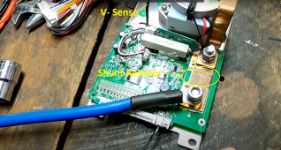
Again my take on this 20A current. There is NO WAY for QUCC to detect this incoming current if the relay is open.
The shunt resistor is between B- and Relay. With Relay Open, there is no current through the Shunt Resistor.
It is V negative Sense that detects incoming voltage from SCC/Inverter.
1654813496288.png

The only way for QUCC to indeed detect 20A with open relay is when the contacts are welded.

Personally, I am not convinced these are defective. And without further clues "use other BMS."
 
Again my take on this 20A current. There is NO WAY for QUCC to detect this incoming current if the relay is open.
The shunt resistor is between B- and Relay. With Relay Open, there is no current through the Shunt Resistor.
It is V negative Sense that detects incoming voltage from SCC/Inverter.
View attachment 97954

The only way for QUCC to indeed detect 20A with open relay is when the contacts are welded.

Personally, I am not convinced these are defective. And without further clues "use other BMS."
There's a separate sensing wire, that checks the external side of the relay.
 
How are you determining the BMS needs 20 amps to turn on?
Once the BMS relay has tripped and opened the common port there will be no voltage applied to the charger. Could the problem be caused by the charger?
Following a shutdown the 'restarting ' conditions will be a reconnect voltage ( perhaps set at 50 volts, see BMS perameters) a current flow, typically a few amps.

Some chargers will not generate an output unless they 'see' the battery.

Mike
In fact the BMS cuts the charge (or I cut the charge manually to to a test). Then the BMS want to allow the charge again (or I manually allow charge again). The app reacts as it should, showing charge is on with the displayed on off button for charge. So for the BMS logic the relay shgould be closed. And for my own logic too. And for everybody logic too.
But in fact the relay does no close (no noise, no led telling it is closed in the corner of the BMS and battery not connected when I measuure current). But when I increase the charge current to about (not very precise) 20A, the relay closes. Below 20A it stays opened. When my charger increase the amperage it increases the voltage too. But the BMS does not react to voltage because it does the same with different voltages. So I think it reacts to amperage as I always have to pass about 20A to close the relay.
I thought about charger (good idea) but I have 3 batteries in parallel so in fact the charger detects the 2 other batteries and continue to send current even when the third one is disconnected by the BMS. When the 2 other batteries need charge and there is a lot of sun, the charger sends more than 20A and the BMS can close the relay. When the 2 other batteries do not need to charge or when the sun has low power the charger sends less than 20A and the relay stays opened until next day the charger sends 20A or more. What is silly (as the batteries have plenty of power to command the relay).
 
That would be the V- Sense indicated in the screen shot.

But this sense wire is not used to measure current.
and only with the help of B+ can it detect the voltage of external devices (SCC or inverter).
In fact I am quite sure the BMS does not wait for 20A to close the relay. So it has not to measure it (so this wire can measure voltage only). The BMS just seems to need 20A because of a bad design.
I think so because on the app tells me the relay is closed (charge and discharge buttons are on) so the BMS believe it closed the relay. But in fact the relay manage to close only when the charger sends more than 20A charge. Apart a bad design, I can not understand this silly behaviour. And of course all parameters are default ones to avoid a problem with parameters.
 
Last edited:
Again my take on this 20A current. There is NO WAY for QUCC to detect this incoming current if the relay is open.
The shunt resistor is between B- and Relay. With Relay Open, there is no current through the Shunt Resistor.
It is V negative Sense that detects incoming voltage from SCC/Inverter.
View attachment 97954

The only way for QUCC to indeed detect 20A with open relay is when the contacts are welded.

Personally, I am not convinced these are defective. And without further clues "use other BMS."
Hello as I told before I do not think QUCC has to detect 20A. It just NEED 20A.
And I am sure the contacts are not yields because when I have 20A or when I reboot the BMS the relay can close and when there is a trouble detected by the BMS it can open it.
I am more an more sure this BMS has a conception problem : it should not but by design it just need the charger sends 20A to be able to close the relay. I don't think they are defective products because I have 3 of them with the exact same behaviour and the third one was bought 4 monthes after the 2 first ones when I added a battery (at that time I never saw that these shitty BMS can not reconnect the battery until they get at least 20A from the charger).
 
Last edited:
Thing is, if the contactor is open, there is no 20A passing because an open circuit cannot pass any current at all.
 
What charger do you have? And where do you set the 20A?

The BMS can only sense voltage when it’s relay is opened. So that “20A” thing/problem is in your charger.

I think the problem is most likely in your charger that can’t see a battery because of the opened relay. It can only see the battery via that high resistance V-sense wire.
Plus, you can only change the situation by altering something in your charger (not the bms).

I think the bms is waiting for some 50-100 mA from the charger to close the relay. And the charger wants to charge, but is testing the battery with a voltage and current limiter waiting for the right conditions.
By raising the charging current setting, the test conditions for the charger are also raised. Which at some point delivers enough current for the relay to close? Me guessing….

A BMS with mosfets doesn’t have the above problems.

(Btw: conception=design in English.)
 
Last edited:
What charger do you have? And where do you set the 20A?

The BMS can only sense voltage when it’s relay is opened. So that “20A” thing/problem is in your charger.

I think the problem is most likely in your charger that can’t see a battery because of the opened relay. It can only see the battery via that high resistance V-sense wire.
Plus, you can only change the situation by altering something in your charger (not the bms).

I think the bms is waiting for some 50-100 mA from the charger to close the relay. And the charger wants to charge, but is testing the battery with a voltage and current limiter waiting for the right conditions.
By raising the charging current setting, the test conditions for the charger are also raised. Which at some point delivers enough current for the relay to close? Me guessing….

A BMS with mosfets doesn’t have the above problems.

(Btw: conception=design in English.)
I have this one
And I set the 20A nowhere. It is just that this BMS seems to need at least about 20A current given from the charger to be able to close its relay when working. As it si not normal at all there is no parameter relative to these 20A.

>I think the problem is most likely in your charger that can’t see a battery because of the opened relay.
It is not the case because I have 3 batteries in parallel and the 2 other batteries are still connected to the charger so the charger continues to send current to them (except when they arev already full). But at the end of the day, when the sun is low, the charger gives less than 20A per battery so the relay cannot close. When it tries to give 10 A to the battery proetcted by this BMS, the relay stays closed (but in the app the relay is told as closed so the BMS think it managed to close it, it is just that, as it is a crappy Chinese product, it could not manage to close !). It is just a bad DESIGN (thanks) I think. The relay should close itlself using the battery energy but it does not, it is like it needed the charger energy to close.
 
Thing is, if the contactor is open, there is no 20A passing because an open circuit cannot pass any current at all.
As I explainded many times it is obviouly not the problem. There is current passing even when the relay if closed because they add a small wire that sense the outside voltage at least to overcome this trouble (without that the relay could never close back). And when the charger gives less than 20A the relay stay opened. It closed only when the charger gives more current, about 20A or more. Or when I restart the BMS. So I am quite sure it is a firmware or a design trouble. But QUCC support told me that is is just that this is a crappy product that is not designed to work with solar system (after I bought theses BMS of course !!!!).
 
In fact I am more and more sure I have badly designed BMS (= crap). Because I bought a NEEY 4A active balancer and saw too late that offgridgarage test tolmd us this product is crap too. So I asked to cancel the order. The the company told me that the new version was OK now. In fact it is version 4 and they sold v1 v2 and v3 that were badly designed ! They tell themselves they scammed customers before v4 (because of course they refuse to refund most of the time) ! Chinese companies are totally unreliable. Beside as their prices go higher and higher every year, they will loose all their clients. Good for western countries.
 
I observe similar misbehavior when testing this same BMS for discharge. Using the charge/discharge buttons, I can disable discharge, the relay opens and discharge stops, which is correct. Reenable discharge, and the app reports that discharge is enabled, but without a sufficient load the relay stays open and there is no discharge. Increase the load and the relay closes and discharge occurs. My load is crude, DC light bulbs in series, and while 100 W is insufficient, 200W allows the relay to close. The pack is 24V nominal.

The QUCC log is also pretty useless. As is the manual.

Not pleased. After reading this post I am sure there will be a similar issue with charging as Cynus reports. Does anyone know why Andy at Off-Grid Garage still has the QUCC contactor BMS listed on his site after finding the issues reported in the video earlier in this post? Is there a follow up video (or better, a written report!).

So this BMS will act as a protection device, but it seems that returning from the protected state will be problematic. At least it is cheap and I only bought one. Anybody want to make me an offer?
 
Back
Top