diy solar

diy solar

Questions about using Renogy 3000 Watt Inverter

richardw

New Member
Joined
Feb 21, 2021
Messages
45
As I am building and learning and testing, I have a few questions about using the Renogy 3000-Watt Inverter. So far, things are running well overall, and I am pleased with the output and capacity that my LiFePO4 batteries are providing.
  • What is the best connector to use to connect the 10 AWG stranded copper wire to the ground post on the back of the inverter?
  • Is there any reason why it would not be good for me to connect the 10 AWG grounding wire from the inverter to its own grounding connector on the copper water line coming into my home?
  • Is it okay to wire the high output terminals to a simple 30-amp receptacle for connecting higher-powered devices, such as refrigerators, freezers, microwaves, etc.? If some kind of breaker is recommended, are there some simple, low-cost breakers that could be used for this purpose. I will be sure to keep the total current draw within the specs of the inverter.
 
As I am building and learning and testing, I have a few questions about using the Renogy 3000-Watt Inverter. So far, things are running well overall, and I am pleased with the output and capacity that my LiFePO4 batteries are providing.
  • What is the best connector to use to connect the 10 AWG stranded copper wire to the ground post on the back of the inverter?
Is this for a chassis safety ground post, or the main negative DC input post? Do you have a picture of it? If it's just a chassis safety ground then 10 awg seems fine, but if for the main DC input, 10 awg is way too small for 3000w...

On connectors, I usually just buy some kit like this (but you need a larger crimper for these at first link):

8 awg or larger:

Or 10 awg:


  • Is there any reason why it would not be good for me to connect the 10 AWG grounding wire from the inverter to its own grounding connector on the copper water line coming into my home?
I would not prefer to ground anything to a water line (in case if there's any current ever going through it), it could influence electrolysis onto the water pipe and water, which could cause corrosion. MAYBE on a safety ground, if you confirm that current never travels on it normally, you possibly could use it as a convenient ground, but I caution about running any current habitually traveling on any water line, as I've seen damage happen from electrolysis in the past.


  • Is it okay to wire the high output terminals to a simple 30-amp receptacle for connecting higher-powered devices, such as refrigerators, freezers, microwaves, etc.? If some kind of breaker is recommended, are there some simple, low-cost breakers that could be used for this purpose. I will be sure to keep the total current draw within the specs of the inverter.

You could easily wire in a larger receptacle (EDIT ADDED IN: up to 20a on 120v), you should get an auxiliary (small) breaker box with one or more breakers in it to protect circuits / cables between there and inverter.
 
Last edited:
As I am building and learning and testing, I have a few questions about using the Renogy 3000-Watt Inverter. So far, things are running well overall, and I am pleased with the output and capacity that my LiFePO4 batteries are providing.
  • What is the best connector to use to connect the 10 AWG stranded copper wire to the ground post on the back of the inverter?
  • Is there any reason why it would not be good for me to connect the 10 AWG grounding wire from the inverter to its own grounding connector on the copper water line coming into my home?
  • Is it okay to wire the high output terminals to a simple 30-amp receptacle for connecting higher-powered devices, such as refrigerators, freezers, microwaves, etc.? If some kind of breaker is recommended, are there some simple, low-cost breakers that could be used for this purpose. I will be sure to keep the total current draw within the specs of the inverter.
This one https://www.renogy.com/3000w-12v-pure-sine-wave-inverter/ ?
 
Are you using the same 10 gauge wire to connect the positive and negative battery terminals? 10 gauge is in no way acceptable for the number of amps a 3000W inverter can pull.
1641408411259.png
 
Is it okay to wire the high output terminals to a simple 30-amp receptacle for connecting higher-powered devices, such as refrigerators, freezers, microwaves, etc.?
NFPA prohibits “temporary power cords used as a permanent means of power” and romex (solid copper) is prohibited by NEC for ‘extension cords’ ie temporary power cord. FYI

You could use a 10AWG cord wired into a portable “handy box” with the proper connector. The metal box would have a GFCI receptacle feeding other duplex receptacles and you could plug your equipment into that.
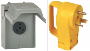
I don’t think you can find standard US receptacles rated at 30A though. The several 30A cord ends and receptacles are not compatible with standard US household equipment.

Yeah that's a good point to clarify, and I had been thinking more along the lines of having an aux panel, and you can have a couple breakers in it (for the AC circuit loads), and do a couple of short conduits out to 15a or 20a receptacles (as you can't do 30a on 120v).

A 20a is 2400w, and a 15a is 1800w.

(I put in an edit to clarify on my previous post above, as 'big plug' was kind of misleading)...
 
Last edited:
Is this for a chassis safety ground post, or the main negative DC input post? Do you have a picture of it? If it's just a chassis safety ground then 10 awg seems fine, but if for the main DC input, 10 awg is way too small for 3000w...

On connectors, I usually just buy some kit like this (but you need a larger crimper for these at first link):

8 awg or larger:

Or 10 awg:


I would not prefer to ground anything to a water line (in case if there's any current ever going through it), it could influence electrolysis onto the water pipe and water, which could cause corrosion. MAYBE on a safety ground, if you confirm that current never travels on it normally, you possibly could use it as a convenient ground, but I caution about running any current habitually traveling on any water line, as I've seen damage happen from electrolysis in the past.


You could easily wire in a larger receptacle (EDIT ADDED IN: up to 20a on 120v), you should get an auxiliary (small) breaker box with one or more breakers in it to protect circuits / cables between there and inverter.

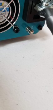
I am attaching a photo of the back of the inverter showing where the ground is to be connected. It is just a screw post with some nuts. It doesn't seem like it was designed to carry much current. Do I just attach a ring terminal in between the nuts and call it good? Renogy specifies a 10 AWG stranded and insulated copper wire for the ground.

I ask about the copper water line because that is what my house originally had as a ground. When I replaced the water main shutoff valve a number of years ago, I had to replace the heavy gauge copper wire bridging the connection from above and below the valve. A couple of years ago, I had to replace my outdoor power meter box because one phase of the electrical power blew. At that time, I had to add two large grounding rods tied into the new outdoor power main box. With my batteries, charger, and inverter all inside the house, I am trying to find a good way to ground the inverter.

I was wondering if there is a good inexpensive way to add breakers to the loads coming from the inverter high output terminals. The only boxes I am aware of that look like a regular breaker panel in a home can be a little costly, and I don't have this equipment in a final location yet. I am still earning and testing.
 

Attachments

  • 20220104_184843.jpg
    20220104_184843.jpg
    52.7 KB · Views: 12
Are you using the same 10 gauge wire to connect the positive and negative battery terminals? 10 gauge is in no way acceptable for the number of amps a 3000W inverter can pull.
View attachment 78439
No, all of my cables carrying the loads from the batteries to the inverter are properly rated. My BMSs are 120-amp models from Overkill Solar. There are three 8 AWG cables hydraulically crimped together by Overkill Solar connecting the BMSs to the 300-amp bus bars on the negative side. There are 2/0 AWG cables from the positive terminals of the batteries to the bus bars, and there are 2/0 cables connecting the bus bars to the inverter terminals.
 
NFPA prohibits “temporary power cords used as a permanent means of power” and romex (solid copper) is prohibited by NEC for ‘extension cords’ ie temporary power cord. FYI

You could use a 10AWG cord wired into a portable “handy box” with the proper connector. The metal box would have a GFCI receptacle feeding other duplex receptacles and you could plug your equipment into that.
I don’t think you can find standard US receptacles rated at 30A though. The several 30A cord ends and receptacles are not compatible with standard US household equipment.
At present, this is not permanent power. This is also a backup battery solution that would be used when grid power is unavailable. I have read that it is not advised to put refrigerators and microwaves on GFCI circuits due to the kinds of issues I am running into when testing with the microwave. Right now, I am testing and want to make sure that what I have will work properly when I need to depend on it. I can make more permanent wiring connections in the near future once I determine where the final location of the equipment will be. In the meantime, I want my testing to follow proper safety standards and also be flexible. My batteries and inverter should be able to handle the microwave and refrigerators with no issues based on my understanding. If I need to add another 12-volt battery to increase the surge amp capabilities, I can do that at some point in the near future. I am also considering the possibility of switching to 24-volt and keeping some 12-volt capabilities for portability or running other devices outside the home, if needed, such as an RV type water pump or other miscellaneous items.
 
Yeah that's a good point to clarify, and I had been thinking more along the lines of having an aux panel, and you can have a couple breakers in it (for the AC circuit loads), and do a couple of short conduits out to 15a or 20a receptacles (as you can't do 30a on 120v).

A 20a is 2400w, and a 15a is 1800w.

(I put in an edit to clarify on my previous post above, as 'big plug' was kind of misleading)...
There are 30-amp to 15-amp adapters for RVs. I have a couple of these from an RV and travel trailer we used to have. I will check into what may be the least expensive solution to power these kitchen appliances from the inverter while maintaining safety. I am aware of what gauges of wiring need to be used and distance limitations, etc. I was hoping maybe there is some portable and inexpensive breaker solutions when using extension cords. My main extension cords are all 10 gauge.
 
Also, does anyone know why my microwaves rated as 1200-watt models are pulling 17 amps? One is rated at 12.4 amps, and the other is rated at 12.3 amps. However, when tested with my Klein clamp meter, I am seeing them consuming ~17 amps. I don't understand how the specs can show them rated at 12.3/12.4 amps input yet are pulling 17 amps in actuality.
 
I am attaching a photo of the back of the inverter showing where the ground is to be connected. It is just a screw post with some nuts. It doesn't seem like it was designed to carry much current. Do I just attach a ring terminal in between the nuts and call it good? Renogy specifies a 10 AWG stranded and insulated copper wire for the ground.
Yeah, that is just a safety ground, should never have current going through it provided that your main cable negative is good.

I ask about the copper water line because that is what my house originally had as a ground. When I replaced the water main shutoff valve a number of years ago, I had to replace the heavy gauge copper wire bridging the connection from above and below the valve. A couple of years ago, I had to replace my outdoor power meter box because one phase of the electrical power blew. At that time, I had to add two large grounding rods tied into the new outdoor power main box. With my batteries, charger, and inverter all inside the house, I am trying to find a good way to ground the inverter.
You'd probably be fine in this case to use it as a safety ground for the inverter, as there shouldn't be current going through it normally. When you get it all installed, you could just double check the ground with an amp-clamp probe and make sure no current flows through it once you are done (indicating some power is escaping through ground). It may not hurt it, but I prefer not to use water pipes to flow power through. And definitely would never use it as an AC ground, but for low voltage DC safety ground, shouldn't purpose any risk.

I was wondering if there is a good inexpensive way to add breakers to the loads coming from the inverter high output terminals. The only boxes I am aware of that look like a regular breaker panel in a home can be a little costly, and I don't have this equipment in a final location yet. I am still earning and testing.

Like this:

Images:
 
Last edited:
There are 30-amp to 15-amp adapters for RVs. I have a couple of these from an RV and travel trailer we used to have. I will check into what may be the least expensive solution to power these kitchen appliances from the inverter while maintaining safety. I am aware of what gauges of wiring need to be used and distance limitations, etc. I was hoping maybe there is some portable and inexpensive breaker solutions when using extension cords. My main extension cords are all 10 gauge.

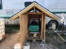
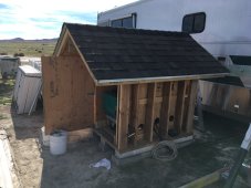
Yeah, I forgot about those RV 30a plugs (was thinking household there). I bought a homemade generator cart a guy made using an Onan 6.3 kW propane generator, and they put on a little 2-breaker box on the cart, and ran one breaker to a regular 15a household receptacle (box), and the other breaker goes to the 30a RV receptacle (other box), and so I can plug in my motorhome RV cord (using a short adapter cable). But it works fine, that should be fine to do. Just treat it the same as the RV 30a connection.

1641450877423.png
 

Attachments

  • 1641450561668.jpeg
    1641450561668.jpeg
    256.2 KB · Views: 6
  • 1641450983352.jpeg
    1641450983352.jpeg
    211.2 KB · Views: 7
Last edited:
Back
Top