


You are using an out of date browser. It may not display this or other websites correctly.
You should upgrade or use an alternative browser.
You should upgrade or use an alternative browser.
Rack feedback
- Thread starter Aakelley
- Start date

That dimension unistrut may be ok for stationary applications but for transport I think each individual beam should be strong enough for no flexing to occur.....nothing less than 40 X 40 X 1.6mmWill this be robust enough or do I need to add more to stiffen it?
Last edited:
Aakelley
New Member
- Joined
- Feb 3, 2022
- Messages
- 140
Yeah it seemed a little too flexible at the mid point. I’m thinking of either sandwiching each unistrut between a couple of 1x1x1/4 steel angle OR swapping the strut out for some 8020 - whichever is cheaper.
Or do you think just the “taller” strut made of 12 gauge might suffice.
Or do you think just the “taller” strut made of 12 gauge might suffice.
Last edited:
acdoctor
Solar Enthusiast
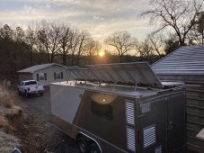
Are we to assume there will be 3 more panels to the left in picture? Will the larger flat screen frame work on the curved roof? Why the odds frame spacing?
From my research support crosswise of panels should be approximately 25% from each end. Frame would be a lot more ridged if you could manage a center support (connection to the roof).
If I were to start over I would use large panels like you have cross wise of the vehicle that could tilt at least to one side. Here at winter solstice one properly tilted 400 watt panel produces as much as 2000 watts flat.
Attachments
Aakelley
New Member
- Joined
- Feb 3, 2022
- Messages
- 140
Yep - 3 more panels.
I’m running vertical supports (1.5 x 1.5 x 1/4 angle) off the ribs that this will bolt into. Just really trying to avoid putting holes in the roof ;-)
Going to try some ways to make the free span more rigid. Failing that, will bite the bullet and attach to the roof at the center high point.
Space I have for panels is 95 x 165. Panels are 39 x 65. I think the only way they will all fit is this way?
Last edited:
Aakelley
New Member
- Joined
- Feb 3, 2022
- Messages
- 140
OK. Take 2.
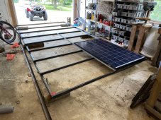
Using 1x2 .125 thick rectangular tubing as the cross beams on ~25 inch centers with the unistrut only for solar attachment points. 1x2s will be welded in by a really good welder friend I have. Unistrut will be bolted to 1x2s. Panels will attach to unistrut with frame clamps. Whole thing will 1/2 inch bolt to 8 (4 each side) 1.5 angle (.125 thick as well) that is river nutted into two spots for each support with 3/8 bolts.
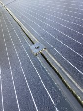
Only part I am still a little tentative on is the solar panels are sitting on two edges of the unistrut. Would like to see them have a little more support. Could bolt all three to the strut in the mounting holes and then bolt the strut to the beams, skipping the clamps.
From all the load and deflection calculations I’ve done, this seems robust enough.
What flaws do you see? How could I make it better?
Using 1x2 .125 thick rectangular tubing as the cross beams on ~25 inch centers with the unistrut only for solar attachment points. 1x2s will be welded in by a really good welder friend I have. Unistrut will be bolted to 1x2s. Panels will attach to unistrut with frame clamps. Whole thing will 1/2 inch bolt to 8 (4 each side) 1.5 angle (.125 thick as well) that is river nutted into two spots for each support with 3/8 bolts.
Only part I am still a little tentative on is the solar panels are sitting on two edges of the unistrut. Would like to see them have a little more support. Could bolt all three to the strut in the mounting holes and then bolt the strut to the beams, skipping the clamps.
From all the load and deflection calculations I’ve done, this seems robust enough.
What flaws do you see? How could I make it better?
Attachments
acdoctor
Solar Enthusiast
They sell unistrut that is 1 and 13/16 square. I think it is just as ridged as the rectangle tube. It might trim some weight and hight. If you stay with the rectangle tube you could just weld a long bolt on the side of the tube sticking up above the top of the panels and delete the unistrut.
Aakelley
New Member
- Joined
- Feb 3, 2022
- Messages
- 140
Tell me more about welding a long bolt? Not following exactly. Any pics that are close?They sell unistrut that is 1 and 13/16 square. I think it is just as ridged as the rectangle tube. It might trim some weight and hight. If you stay with the rectangle tube you could just weld a long bolt on the side of the tube sticking up above the top of the panels and delete the unistrut.
acdoctor
Solar Enthusiast
With accurate measurements located a say 1/4 20 x 4” bolt vertical on the side of the of the rectangular tube with the side of the head just below the tube so the bolt lays flat. Or cut the head off weld it in place. It would point up between and at the edge of the panels. I did similar but with the the bolt inverted and not welded.
Attachments
acdoctor
Solar Enthusiast
They could be cut angle but you may need to trim the one leg. Mine are bent aluminum the vertical leg is the exact hight of the panels. The mid panel is just a piece of flat aluminum.
HARG Hunter
Thirsty for Off-Grid Knowledge
Looking to build something very similar to this for my house roof.
Doing 1 roof that already is good angle, but another roof is a little flat, so I will build in an angle.
Any info on how to create stand-offs to get them a few inches away from the roof?
Doing 1 roof that already is good angle, but another roof is a little flat, so I will build in an angle.
Any info on how to create stand-offs to get them a few inches away from the roof?
Hedges
I See Electromagnetic Fields!
- Joined
- Mar 28, 2020
- Messages
- 20,535
Only part I am still a little tentative on is the solar panels are sitting on two edges of the unistrut. Would like to see them have a little more support. Could bolt all three to the strut in the mounting holes and then bolt the strut to the beams, skipping the clamps.
I have the same concern with how I plan to connect two panels side by side with bottom clips and Unirac rails. Rail is meant to be under middle of a rail with either bottom clip bolted through hole in frame or top clamp. I normal configuration, one rail holding left and right sections of frame keeps their spacing fixed relative to each other. With rail parallel to frame as I plan, frame might slip off rail, and glass laminate might pull out of frame.
What I will do is have a sheet of aluminum spanning from bolt through frame of one panel to bolt through frame of other panel. That keeps frame from slipping off rail.
Also, straps joining the orthogonal frame at end of panel to frame of other panel, keeping (flexible) rails at constant spacing.
My objective to to assemble array with fewer rails. A 6 x 4 array will have 7 rails for 6 panels across, and 4 panels tall extends beyond end of rails.
For your configuration, maybe aluminum straps between panels on sides of bottom of frame. Even self-tapping stainless screws through frame could do it.
What flaws do you see? How could I make it better?
Rust prevention. Hot-dip galvanized unistrut is supposed to be good for 20 years, electro-"galvanized" about 5 years. The angle iron in your picture is uncoated. I assume you plan for a good metal treatment followed by paint. But welded joints would mean faces of material where you'll never get paint although water will find it. Maybe a full bead sealing all edges can make those joints water tight. Possibly unistrut with no holes punched would be better. Maybe welded ends on the unistrut which can bolt to angle or other unistrut, rather than entire assembly welded.
You can also get aluminum unistrut.
Aakelley
New Member
- Joined
- Feb 3, 2022
- Messages
- 140
Good idea. I think I could I use the mounting locations that are predrilled in the frame (total of 8 - four per side). The panels are 39" wide, so 4 x 43" aluminum straps that connect to each mounting hole on the frame and then into the unistrut. Would help make the install easier as well since the final bolts that needed to be tightened would all be accessible and facing up.For your configuration, maybe aluminum straps between panels on sides of bottom of frame. Even self-tapping stainless screws through frame could do it.
Totally plan to treat and paint all the angle and beams. Plan to full bead all edges when welding / use rod to fill in small gaps. Will see whether I can get some aluminum unistrut.Rust prevention.
Thanks for the detailed feedback!
Aakelley
New Member
- Joined
- Feb 3, 2022
- Messages
- 140
The one alternative I am pondering is to just ditch the unistrut altogether and use simple l brackets made from cut angle to bolt the panels directly to the 1x2s. I am a little squeamish about drilling holes in the sides of my panel frames though...
Hedges
I See Electromagnetic Fields!
- Joined
- Mar 28, 2020
- Messages
- 20,535
Safer than drilling the bottom!
Use a reliable depth stop if you need to drill the bottom. I once got some plastic Jacobs chucks supposed to serve as drill stop, but they slip. A simple length of copper tube over a drill bit bearing on jaws of the drill's Jacobs chuck is good.
The implementation depends on access. You have an inch between panels and roof. I use a ladder to access panels on ground mount so bottom clips. On house roof I will use top clamps, although I have reached under and used bottom clips or Unistrut clamps before. (did Unistrut on a customer's roof, with penetrations only at the ridge and eaves to minimize leak issues and flashing.)
When I first came up with the concept of panels in portrait orientation with one rail under the edge of two adjacent panels, I missed the issue that frame can slip off PV glass laminate. Frame is only held together in the corner with tiny screws. So I thought of tying the other frame pieces together between panels. Haven't built it yet.
I have ordered some angle aluminum and bolts from McMaster-Carr, to assemble more copies of the ground mount I got from Unirac. On-line metals may be more economical. And I get some hardware from various eBay vendors.
I like rails with slots that clips or clamps fit into. Convenient to adjust positions. I used Unirack, similar available from Iron Ridge. Unistrut also makes PV mount hardware for their rails.
Aakelley
New Member
- Joined
- Feb 3, 2022
- Messages
- 140
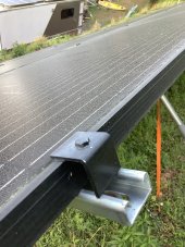
So still mocking things up. Most of the stuff in this pic is not for “production use” (the carriage bolt, the unistrut namely). Wanted to see what I could do with some of the left over 2x2 angle. This is a super quick and dirty pass at an edge clamp.
Could I make a bunch of these and clamp directly to the beam? Maybe use a rivnut in the beam to not have a nut to deal with? Would be 3 per side on the two end ones, 2 each side on the middle ones and 2 flat plates between the ends and the middle on the short edge of the panel.

Could I make a bunch of these and clamp directly to the beam? Maybe use a rivnut in the beam to not have a nut to deal with? Would be 3 per side on the two end ones, 2 each side on the middle ones and 2 flat plates between the ends and the middle on the short edge of the panel.

Hedges
I See Electromagnetic Fields!
- Joined
- Mar 28, 2020
- Messages
- 20,535
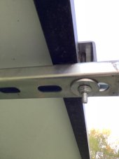
That will have a bit of weight swaying on 30" tall vertical supports.
It is going to be welded not bolted, but how about diagonal braces in X and Y direction?
Make sure no sparks can land on windshield. Been there, done that.
Me, probably couldn't ever weld a tank so it is air tight. You have a large gap between end of rectangular tube and angle, difficult to fill while welding. Right angle corner cut on square pipe and inside radius of angle contribute to that.
Aakelley
New Member
- Joined
- Feb 3, 2022
- Messages
- 140
Yeah, may add some diagonal straps. Easy enough to do with it all being bolted in. The verticals are angle and are bolted into the ribs in two spots with 3/8 grade 8 bolts.
I’m going to weld the rack on the ground so I can really clean it up after and paint it well. The rack weighs right at 200 lbs so getting a few of my buddies to come over and help install it once its built, cleaned and painted. This was just to make triple sure that the beams were the right length. Measure twice, cut once....but measure 3x and mock up twice before you weld!
Am going to grind down the end edges of the beams to fit in the fillet of the angle.
Last edited:
Similar threads
- Replies
- 1
- Views
- 122
- Replies
- 2
- Views
- 394
- Replies
- 7
- Views
- 396
- Replies
- 2
- Views
- 192