diy solar

diy solar

Rate my battery?

shortyjacobs

New Member
Joined
Mar 8, 2021
Messages
21
I'm brand new to this and learning as I go. Got in 4x 202AH cells from BLMPOW on aliexpress, working on charging them up. Cells, by the way, look great, come with m6 posts that look welded on. Was top balancing from scratch, thinking "5 amp rate, 202 ah, max time will be 20 hrs....", while forgetting that I had them in parallel. Duh.
tXEgO99MS3JDk-D99sf9E9htcpoy9BWN2ftN8FeRCNfHaIWVqw5HUiLW5hwcMhqPzewwljeRr29H5pMGXzxDGHM4PPd2GMZlU7zYAipmfAvp_hOGJ3GvlhtqOISgQxwMzWqrWH1ebtZGorRl9a2UpxfJh3U2xOtS7uBERyxtCBKNYvxquHUz7Vb2jy5GtIXsVFdfyPBiXkDzsgpWHibFoH5TG2786xYfcVWkc2mGcaIh3_t_12wSRrogd7V0_T86JP9sdklollf4gYMXKK39t-TW94Vuqnf0Ptj9o6mE1M4ClxfuQZj-EJhNXFaPVP9EmqVEr3AxpumlU8TZ6Uj3mEh3SNwwNSssua3X4yqgoQU4w33XYzsQ9xWlZ1_NGuouABYBiZyhI4q1w8qASc2zWSUqaksVN9UQEs52AlWheuM52Jevneoum6ldEIrp0BYrm4oc5YP3tBXx0npPiKB0wV9QfDlUxKYmSUj-3FuacSmbxT8fh0kDenHnhWJxslTk3SV0TDgWBWGM8uJxeBkAve1_ptKPhf9MybT_yVpH2-5GMSV9uXEVcFJxfYfRg2h-to7F41azJVTucHJpkt4tixnGcbeqfJMTs07BWLhcS4Yl7qdwrFV7BHEBeK9ReKEeOCBH6MT8wjtDxbUR4dPm42IQOXof3A_8zF2eWbCojzSHQztI_bPf9ZmvEPA_nFq-R74bHmqLwTKZaj3zhOGgyY1qTQ=w1346-h1009-no


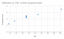
Decided I wanted a compression frame, hook up the overkill BMS, and series charge them up to HVD on a cell before doing the top balancing. Figured foam was a good option - saw the thread on foam compression frames, but didn't want to pay for the expensive Granger foam, (or wait for it). Got quarter inch neoprene from Amazon, prime, and did a quick pressure/compression calibration:
Vtl66IoG7JFSTkZwfO5d5b5Ni7H_zJesV99r8o0zpctd_kNnHOP1aJQxka-KZzAUZttM6yaIVmDs70X4VP_Ay_ZKcrcwGgCplxtmINaKIkHy4DTmOOGMaZkSNAEsdNSbH2VUk1Zeysmqo1HjS_vkJkyad7Dss0V-DkRjlWJGwPUGrqp7G6-Cd_prnM7swxolxLY-MKD8U6nEiLP7B9mXNLPmM1qMXiXqgoaz89isXUrHh3NTaAGWXgnfOaALSFJT0MMY5944qhgIF3uz_fWneLkh6acLSj2nyB4Us9t7LCRAMVaNtsKZtc9lvpia0DaKDAMfp3zYfpuYYXZkzn7E1MBhu7tkv02JShW04lI-L7efTwhPjcxtchWp_gGYwtd9ljQlDtsJ6aAxtpAkkNGynUCcQ67hph3KTJVay2sA1-lod62EMKg60l7Wu-dqI2PZKhfaiiOoIysX7A91B0UOb_Pt2jhFcpB0OwfQfDRhK8MvR_2ni9euInpeWCtM099zQPwtpUpyXG3xBOqb25gy-g3O3ahb6qznyw4Lh6mVv73vLrzTqbOwD0e4Q1l8HRXvvuBcHZCYm7XzwI3lpJq7pPAqhDilc6nirh-hc1YRARV0DMz5IhpDrQ2r1MoLb3zp2xskgQVlpF3ceScj0klE7HOsnGjpdG7k9lMZypwQDiQ94zTznUxrCar3rYYafRtU7-OAgguDeRqTVmbCtl8yOo6Ddg=w727-h969-no
1621437972008.png

Decided I want around 2.4mm per layer of foam compression to get 12 PSI, with a max of 2.8mm and min of 2.0mm. Added up the battery thickness, foam thickness, and subtracted 2.4mm x 5 layers of foam to get a final pack width. I used 3/8" allthread with 1/2" OD polyethylene tubing over it for the compression, and cut the tubing to the exact size I want the pack to be after compression. What do you think? Have I missed something here? Does this look safe/OK?
JqYcbBkXKfGJWF8OnR1bBh9Yinh3YdCITMZkkbOsqVy5xHf4CUq8T-3HEdddPR7chO3JluMm-dCpzU4i4fprqGoHHVDeHIQI21rl09m9SZp0mSJbb1rgq9DTunQThck7bJ7XO3s33kqSg9xEhup8hiZJeSNaJOp0OBBS59mncmagcaXpK-3ge21wkz5Q1QpuV-u3xKRFBb9hdcOcJSkJE69TJpM_CV41poInp4uY5IDFQomcRUweXoAHrv5N9fdUjXz7aeyDNK8c5sAPqP7JUJrchYp0hV-VDpD5EvV4EUYQfeUBV8ykXhpj27sqjJcU3TFkMUzVX77aT0uApE1KgXPDxJ_H-kefmWiM35sxmrwDGkVSejFagoh5CmfoaLb3-Qq-_L8ucCZFct7qUsaV-XVklDZd3yH2B2ru67qzJLQGQUxGUATyJWIf4ibLrL6mh0pTf0A55Yrc2fD_jBAeHUbooOHj0E-gxHvdW3PJTm0KSkPiMyVs_mYRVI_wQfX8u3k-fow3cCxtbQlTA_T1Mhpo5jhquGNDAmJAinILIJWyWTYGP-tdwK8L3-XCOBNoRF9A7ciGfCvUC0j6lpInHPNgNZfIqxS3pXr67X-8flXbhs6USgBv9FQZV3SJKIdgipMCGCHYU_Oa7vfb72VKHRxNdLYZDlqdyve0UJjrUs9vD1ZyXTRNlNSJacI5vcoQ8mJMcTyRDTiZr9ljZdtQXeLvuw=w727-h969-no
 
Those crimps on the big cables concern me.

I thought I was just being a (hydraulic crimper) snob.
cool1.gif


They don't look so good. Heat shrink tape would be like putting lipstick on a pig. OK, they're not THAT bad. Just poking fun at them. If there are going to be problems with the crimps it will be a moderate to high amp draws.
 
Some of your pictures aren't coming through for me.

Nine rods on the compression frame??? That has to be a record!
bowdown2.gif
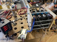
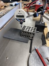
Yeah weird. And I can’t figure out how to edit the post. Oh well, the only one showing something new is the one showing my compression testing setup. Nine rods was because all thread is cheap, and I was going for uniformity.31369AD8-A9E9-436E-95B7-D3D2CDBABFF3.jpeg
I thought I was just being a (hydraulic crimper) snob.
cool1.gif


They don't look so good. Heat shrink tape would be like putting lipstick on a pig. OK, they're not THAT bad. Just poking fun at them. If there are going to be problems with the crimps it will be a moderate to high amp draws.
Yeah, I’m not thrilled. They are hammer crimped, and hammer crimped when the cable was held in a curved shape, (so the crimps wouldn’t be stressed). They hold their shape when not bolted in, so it’s not like that wire is pulling out, it just looks janky. I have some thick arsed copper I can make bus bars out of (20mm x 4mm), but was worried about cell movement with the foam. I was too impatient to wait for braided bus bars…
 
If the crimps pass a pull test, they are probably okay. With a hammer crimper I like to rotate and crimp in three locations.

You can also just heat up the lug with a propane torch and apply a judicious amount of solder.
 
If the crimps pass a pull test, they are probably okay. With a hammer crimper I like to rotate and crimp in three locations.

You can also just heat up the lug with a propane torch and apply a judicious amount of solder.
Oh they are secure. No movement of copper if I pull or bend em. I didn’t realize you could/should do multiple sides with the hammer though, I can definitely do that.
 
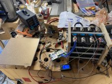
Well just closing the loop. In spite of a goofy capacity test setup, they delivered advertised capacity. Had to use a 12V ~180W heated build plate from an old 3D printer to run the test. Not bad for $380 shipped, and the laser welded studs made things easy.
5B48EFD0-03AD-4367-B17D-F6E47B27FD8D.jpeg
0F76983B-B781-4B52-96B2-9AFF7252E63E.jpeg
 
I did the same charging "miscalculation", and then subsequent re-wiring w/ BMS and then top-balance as you did with my 280Ah cells. I personally think that's the best way to top-balance if you have big cells and don't have a 50A+ charger.

That foam is a good idea. Got a link? I just mounted mine inside the compression frame and called it a day, but your method seems better since it gives you some variance depending on SoC.

Sure, this is what I used: https://www.amazon.com/gp/product/B01JSWJTNY/
 
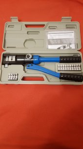
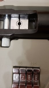
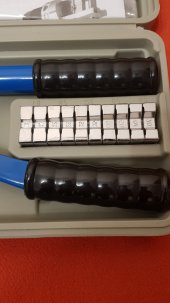
I bought a device like this. You can do everything neatly and reliably with it.
 

Attachments

  • 20210615_224716.jpg
    20210615_224716.jpg
    108.7 KB · Views: 9
  • 20210615_224739.jpg
    20210615_224739.jpg
    77.5 KB · Views: 9
  • 20210615_224751.jpg
    20210615_224751.jpg
    83.2 KB · Views: 9
just heat up the lug with a propane torch and apply a judicious amount of solder.
Then what happens when a fhorst moment occurs and the wire falls out?

if you must solder, mechanically attach it first.

my hammer crimper seems ok. Been happy w/ it. I use a 3# hammer.
I will admit a swaging die would be better - I do get a tight, 100% contact crimp on battery cables which is the only thing I ever use it for.
 
Last edited:
Then what happens when a fhorst moment occurs and the wire falls out?

if you must solder, mechanically attach it first.

my hammer crimper seems ok. Been happy w/ it. I use a 3# hammer. It’s nearly swaged in one shot!
The connection I was referring too was already (if questionably) crimped...
 
Back
Top