diy solar

diy solar

REC BMS Connector

Hi @BretS , I’m planning on turning in my newly assembled system this week.

  • REC Q BMS
  • Victron MPPT with VE.Can
  • Victron MultiPus 24/3000/70
  • Victron CerboGX
I’m hoping you can advise on two questions:
  1. Can I daisy chain the CAN ports starting from the BMS, through the SCC, the MultiPlus, and finally the Cerbo? If so, which ports are used for that?
  2. On first system startup, with all equipment at factory defaults, what happens?
Thanks for sharing,

A.

1. I have mine with the Cerbo as the hub. My REC goes to a VE.Can port, and the Multi-II goes to the VE.Bus port - they are separate cables going in. My MPPTs are on VE direct ports with separate cables as well. Since your MPPT has VE.Can, you can also go to a VE.Can port with that. I am unsure about daisy chaining, but I do know you have to use terminators if you do that. It is in the manuals.

2. I started with my REC on the Cerbo, and got that functioning first with nothing else turned on/connected. It took some trial and error, as the REC instructions had some errors in the Cerbo setup portion. Once that was working, and the Cerbo recognized the REC, I turned on the Multi with an MK-3 VE to USB hooked up to my laptop. I then configured my charging and inverter settings. Then I shut breakers to supply the AC system from the Multi. For the MPPT, connect it to the battery (solar panel disconnects open), and program the charging settings. Then shut the disconnects and you are in business.
Thanks a lot. I hadn't realized that the MultiPlus has VE.bus ports, not VE.can. Oops.

Is the USB dongle really required to configure the MultiPlus or can that be done through the Cerbo?
 
As BretS stated, you can daisy chain VE.Can any way you like as long you terminate the lane (on both sides!) with 120 Ohm 0,25W 5% resistor between pin 2 (CAN low) and pin 7 (CAN high).
Those are readily available to order separate or come with Venus or CCGX and also with REC-BMS (some configurations). Terminating on both sides means you need to plug any free port on devices if present. Usually there are several ports only on hubs like GX or on some other more complex equipment.
Linking everything together and just flip a switch is usually a very, very bad practise. You need to turn on one piece of equipment at time starting with BMS then Cerbo then MPPT and Multiplus at the end all connected to the battery ONLY and set up each device correctly before allowing to do their theng. Even after that it is advisable to monitor behaviour and performance of each device for at least couple of cycles before letting everything work together.
 
Thanks a lot. I hadn't realized that the MultiPlus has VE.bus ports, not VE.can. Oops.

Is the USB dongle really required to configure the MultiPlus or can that be done through the Cerbo?

You're welcome! Glad I could help some.

You have to have an MK3-USB to configure the Multiplus.
 
Thanks a lot. I hadn't realized that the MultiPlus has VE.bus ports, not VE.can. Oops.

Is the USB dongle really required to configure the MultiPlus or can that be done through the Cerbo?
MK3 to USB is required to set up multi correctly. There are some options with DIP switches but no valid set-up can be achieved using those. You can never read (or write) settings of multi without this dongle and that way you are flying blind...
 
As BretS stated, you can daisy chain VE.Can any way you like as long you terminate the lane (on both sides!) with 120 Ohm 0,25W 5% resistor between pin 2 (CAN low) and pin 7 (CAN high).
Those are readily available to order separate or come with Venus or CCGX and also with REC-BMS (some configurations). Terminating on both sides means you need to plug any free port on devices if present. Usually there are several ports only on hubs like GX or on some other more complex equipment.
Linking everything together and just flip a switch is usually a very, very bad practise. You need to turn on one piece of equipment at time starting with BMS then Cerbo then MPPT and Multiplus at the end all connected to the battery ONLY and set up each device correctly before allowing to do their theng. Even after that it is advisable to monitor behaviour and performance of each device for at least couple of cycles before letting everything work together.

The most important step is to make sure the BMS.CAN from the REC to the Cerbo is working. In the Cerbo you can get statistics on this bus to ensure it is working.

Then ensure DVCC is setup correctly. This means it showing the REC as the temp and current sensor and the values are similar to what the REC reports.


All the Victron equipment you plan to use will be configured by DVCC for it's charge voltage settings, and charge/discharge max loads. This comes from the REC configuration. You need to check that it is showing the proper temps and targets from the REC.

You may need to configure some stuff for anything that doesn't use DVCC - like battery protects, etc.

There have been bad cables from REC where the BMS.CAN or VE.CAN did not work as wiring backwards. So you need to check before applying any significant charge/discharge loads.
 
MK3 to USB is required to set up multi correctly. There are some options with DIP switches but no valid set-up can be achieved using those. You can never read (or write) settings of multi without this dongle and that way you are flying blind...

Via VRM you can remotely configure a Multiplus without the MK3 adapter. You do a config download; local edit in ve.configure, and then re-upload via VRM.

You do not need a MK3 any longer.
 
Via VRM you can remotely configure a Multiplus without the MK3 adapter. You do a config download; local edit in ve.configure, and then re-upload via VRM.

You do not need a MK3 any longer.
Uf, thx for a tip. Wasn't aware of that option. But since at time of my multi purchase tis wasn't available (I think) and sometimes internet is limited (in my case in my marina) I always relied on this adaptor without seeking other solution.
Is FW upgrade also available with VRM?
 
Via VRM you can remotely configure a Multiplus without the MK3 adapter. You do a config download; local edit in ve.configure, and then re-upload via VRM.
I was just reading about that. Is the configuration simple text editable or do we need Windows to edit it?
 
I got everything talking to each other and powered up, but with no charge sources. Thanks for the assistance. Next steps is to carefully proof everything.
 
Good to hear you're hooked up C60. In the mean time I was able to follow jwelter99 info and upgraded FW remotely through VRM portal to v.490. Done everything according to instructions during upgrade and I have now some big problems:
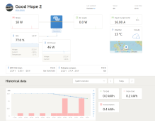
  • Multiplus stays in absorption mode no matter in which SOC is the battery and regardless of cell voltages. It charges between 0,5 and 2 A even if there is a load of apx. 6 A present (3,5 A load on attached picture).
  • Multiplus start charging in bulk only if I cycle the switch on the REC-BMS and it never starts again until next cycle. It just stays in absorption... :censored:. VRM states it's in bulk actually but current never goes up.
  • Parameters on CCGX are correct although there is an odd behaviour and it shows CVL eider 14,1 V or 14,3 V and no correct 14,2 V when cells are set to stop charging at 3,55 V per cell (4x3,55=14,2).
I sent an e-mail to REC to see if they are familiar with this issue. I'll post their answer when received.
In the mean time I turned Victron forum around and although there is some information how to force-switch multi/quattro charge mode it looks like it always switch in absorption (it's in float actually) in my case.
Hope I didn't brick my unit with FW upgrade...
Just wanted to give you all heads-up with FW upgrade!
VRM.1.png
 
When using a BMS that speaks CAN, slave charge sources like SmartSolar SCCs and inverter/chargers basically become CC/CV devices where "bulk" can be translated to "constant current" and "absortion" to "constant voltage". My brain finds that much easier.
 
Oh, I’ve got a drift on it.
If the load is relatively small, CC kicks in lower (SOC). If load is high it starts charging way sooner…
Hm, mistery still needs to be resolved…
 
1. I have mine with the Cerbo as the hub. My REC goes to a VE.Can port, and the Multi-II goes to the VE.Bus port - they are separate cables going in. My MPPTs are on VE direct ports with separate cables as well. Since your MPPT has VE.Can, you can also go to a VE.Can port with that. I am unsure about daisy chaining, but I do know you have to use terminators if you do that. It is in the manuals.

2. I started with my REC on the Cerbo, and got that functioning first with nothing else turned on/connected. It took some trial and error, as the REC instructions had some errors in the Cerbo setup portion. Once that was working, and the Cerbo recognized the REC, I turned on the Multi with an MK-3 VE to USB hooked up to my laptop. I then configured my charging and inverter settings. Then I shut breakers to supply the AC system from the Multi. For the MPPT, connect it to the battery (solar panel disconnects open), and program the charging settings. Then shut the disconnects and you are in business.
Hi Bret, just wonder if you can share specifics regarding Rec/Cerbo setup portion that you needed to tweak to get proper connection, please? I am getting to this part now and don't have any other source of knowledge beside this forum. Thanks in advance!
 
Hi Bret, just wonder if you can share specifics regarding Rec/Cerbo setup portion that you needed to tweak to get proper connection, please? I am getting to this part now and don't have any other source of knowledge beside this forum. Thanks in advance!

The REC ABMS manual has a good description on the canbus setup with the Venus device and specifically the Cerebo. Follow that and let us know if you run into any issues. It covers the required DVCC settings and canbus settings.

I've never seen this part be too difficult to get running.
 
Hi Bret, just wonder if you can share specifics regarding Rec/Cerbo setup portion that you needed to tweak to get proper connection, please? I am getting to this part now and don't have any other source of knowledge beside this forum. Thanks in advance!
Sorry, I've been on the road lately. Like said above, follow the manual and let us know how it goes. I believe they improved the manual after I downloaded mine (I had mine pretty early on).
 
Regarding REC BMS Contactor, can't find description on the wiring in documentation. It has identification +/- in the data sheet and list them as POS and Neg. But the contactor is in my POS+ path between fuse and POS+ bus bar. Is there a specific way it needs to wire for a flow or either way works? Thx.
 
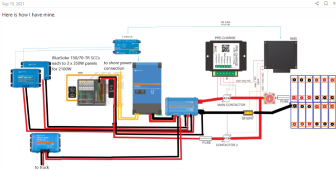
Also, @BretS - I found your diagram in another post, while its very close to my system (without second contactor), the wiring looks different from pre-charge unit then in the manual for the controller? Am I reading it wrong? Here is yours:
1654655153617.png

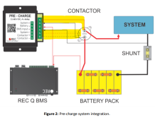
and this is the one form the manual contactor manual:
1654655301716.png
Is there a reason for a difference there? Thanks in advance.
 
That top diagram is wrong. Looks like it should be flipped left to right. Yours is correct.
 
Back
Top