diy solar

diy solar

Renogy 2000w inverter/charger issue?

Katie33kate

New Member
Joined
Jun 26, 2022
Messages
42
I have just replaced my lithium batteries with BestGo 400amp 12v.
it has been a struggle. The first battery had a bad cell and the alarms were ringing at 14.0 v
the replacement battery was at 2.3v. when installed. Vendor claims my inverter/charger cause a massive, instant drain. ??? Honestly doubt it as the inverter/charger was not even on. But, if this is a possible problem source I need to understand it before the next replacement battery shows Up.

has anyone heard of such a thing? I haven’t gotten any detail answer to my questions…the manufacturer is in China and it takes weeks for a simple question to get an answer…then it is followed by more weeks for the next question. I won’t buy this again.

but, meanwhile I am still dealing with battery issues.
can anyone tell me if they have any info about this??
 
I have just replaced my lithium batteries with BestGo 400amp 12v.
it has been a struggle. The first battery had a bad cell and the alarms were ringing at 14.0 v
the replacement battery was at 2.3v. when installed. Vendor claims my inverter/charger cause a massive, instant drain. ??? Honestly doubt it as the inverter/charger was not even on. But, if this is a possible problem source I need to understand it before the next replacement battery shows Up.

has anyone heard of such a thing? I haven’t gotten any detail answer to my questions…the manufacturer is in China and it takes weeks for a simple question to get an answer…then it is followed by more weeks for the next question. I won’t buy this again.

Yes, it's very common and comes up all the time on this site. When you connect a battery to an inverter - even if the inverter is off - there is a massive surge of current to charge the capacitors in the inverter. The LFP battery BMS sees this as a short circuit and enters protection mode.

You need a pre-charge circuit.

This video explains the concept of using a resistor to pre-charge the inverter:


If you disconnect the battery from the system and apply a small charge, the BMS should reactivate, and the battery will report actual voltage.
 
Humm…. That is interesting. I do not know how to apply that knowledge to my system.

my battery is reached from an outside access hatch. The inverter is inside, screwed down to a shelf 24” above the battery.


the battery is connected to a master shut off switch. From there is goes to a power post above the inverter/charger
from the power post it goes inside my rig and directly up to the inverter/charger. But…the posts on the inverter/charger are on the opposite end of the shelf…about 24”. Inside.

the negative side of the battery connects directly to the bottom of the shunt. From there to a buss bar for common ground. From there inside to the far side of the inverter charger. (Up 8” and back 24” to the end of the shelf.

it doesn’t look like I could have this resister on all the time. Could I just take the ground side of the inverter/charger off…install the battery without the ground side connected. turn on the master switch and figure out a temporary ground cable directly from battery ground to inverter ground. Then disconnect it and connect the ground to the shunt. Should the battery remain on all the time after that?

how long does this resistor last? After disconnecting the resistor, would I have 60 seconds to go outside and finish hooking up the battery to the shunt?


it is really common for me to shut off the master switch while I am working on some part of the system….would I have to do this every time I turn it off?

how would I do what Will does in the video?


ok…got an idea… how big does the battery that pre-chargers the capacitor need to be? maybe use a second small, cheap battery to do the job?
 
Last edited:
Thank you. Great reference. I was totally over thinking and over designing this.

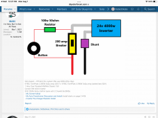
I have a 200amp circuit breaker already on the cable from the power post to the inverter….I will just add a push button and resistor. replace the circuit breaker with one that I can manually open and close. Just like this fellow on the forum shows.
thank you again for the reference.
6DB86AED-253C-4179-9E5F-C4249D743F44.png
 
I just went back to review this. Will (guy in the video) is using the resistor on the negative (ground) side…this little diagram shows the use of the resistor on the positive side. Which is right?

I thought i understood it, but now I don’t.
 
I just went back to review this. Will (guy in the video) is using the resistor on the negative (ground) side…this little diagram shows the use of the resistor on the positive side. Which is right?

I thought i understood it, but now I don’t.

For the stated purpose, it doesn't matter. It's important that the resistor is in the circuit. (+) is preferred as disconnecting the (-) may break ground, but for the purposes of pre-charge and your situation, I don't see a problem.

You could do it at 4 locations:
(+) at inverter
(+) at battery
(-) at inverter
(-) at battery

or any of the components like bus bars, breakers, fuse holders, etc., that are in the battery to inverter circuit.
 
Ok, thank you. I see nearly all the examples I have found are on the +. For me that is much easier to install.
 
Back
Top