diy solar

diy solar

Renogy Battery Monitor 500A Screen Not showing charge rate

Srvprelude

New Member
Joined
Apr 21, 2021
Messages
9
Hello, first off thanks in advance for the help I have spent weeks researching and waiting for renogy's response (they did respond but did not answer my actual question, I left more confused then when I first started, a friend pointed me to this website, greetings! I hope someone here can point me in the right direction)

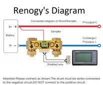
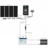
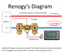
My problem: The renogy battery meter lcd screen will only show a discharge rate with down arrows on the screen, even in full sunlight with no load it never gets the up arrow indicating a charge. I did my best to understand renogy's instruction booklet, I found their cartoon drawing diagram the easiest but doesn't make sense to their verbiage in the booklet, I feel like something is not connected correctly?

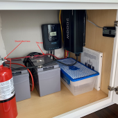
Setup: 4x100 watt renogy eclipse panels on the roof, feeding into a renogy rover 40a charge controller, that feeds 2x100AH renogy agm's in parallel, connected to a renogy 2000w pure sine wave inverter. Last weekend I added the renogy battery monitor screen/shunt in hopes of better accurate readings.

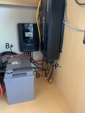
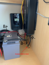
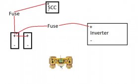
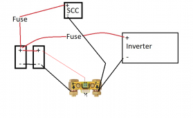
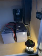
Currently the negative battery post is connected to the -B on the shunt bolt, on the outgoing side of the shunt the -P is connected to the inverter negative in lug, and then the little red B+ wire is connected to the 2nd battery positive post. With how it is wired, it only shows discharge rate. I have done all of the calibration etc, and I set up the max AH as 100 instead of 200 to protect from the 50% discharge rate. Please see photo of my temp install and wiring diagram showing how it is currently connected. What did I do wrong? Anybody run into this issue of showing discharge only, and never charging on the monitor screen?

(I'm heading back out there this weekend April 23rd with tools and hopefully a new plan to wire it correctly, its 160 miles from home)

Thanks in advance -Mike
 

Attachments

  • Diagram.jpg
    Diagram.jpg
    150.8 KB · Views: 129
  • Setup.jpg
    Setup.jpg
    179.9 KB · Views: 125
  • Wiring.jpg
    Wiring.jpg
    115 KB · Views: 134
Welcome to the forum.

Per the Renogy Diagram, SCC (-) must be on P-, not B-

I suspect there are other issues. Please provide a pic of the full battery bank.
 
Welcome to the forum.

Per the Renogy Diagram, SCC (-) must be on P-, not B-

I suspect there are other issues. Please provide a pic of the full battery bank.
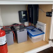
Thank you for the reply, I will be heading back out there this weekend. This is the only battery photo I have saved on my phone.

Can you elaborate more on the wiring I messed up, I’m a noob at this stuff. So the SCC -solar charge controller negative wire is supposed to attach to the charge controller and also to the P-? Does anything connect to the inverter lugs? How does it know what is being used or drawn out? It reads directly from the battery bank then? Sigh... Thanks... I will get there!
 

Attachments

  • 9ABF1695-7A6E-4473-978D-216AD4C2D429.jpeg
    9ABF1695-7A6E-4473-978D-216AD4C2D429.jpeg
    262.3 KB · Views: 53
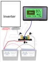
All (-) connections to the battery should be made to P-.

If you connect anywhere else, you're bypassing it, and it can't see the current.

Hopefully this is clear:

1619133824476.png

By having your wires to the inverter connected to the closest battery, that battery will bear the lion's share of the load thus placing greater wear on it. Your main terminals need to be "across" your battery bank.

See "wiring" in link #2 in my signature for Victron's "Wiring Unlimited" resource. They have a section on how to parallel batteries.

I see what appears to be a fuse block between the two batteries. It's not clear what it's for. You should have a fuse between the battery main (+) and the inverter.
 
All (-) connections to the battery should be made to P-.

If you connect anywhere else, you're bypassing it, and it can't see the current.

Hopefully this is clear:

View attachment 46282

By having your wires to the inverter connected to the closest battery, that battery will bear the lion's share of the load thus placing greater wear on it. Your main terminals need to be "across" your battery bank.

See "wiring" in link #2 in my signature for Victron's "Wiring Unlimited" resource. They have a section on how to parallel batteries.

I see what appears to be a fuse block between the two batteries. It's not clear what it's for. You should have a fuse between the battery main (+) and the inverter.
Thank you, this weekend I moved the red positive wire over to the first battery per your recommendation above. The fuse you see is the one that came in the Renogy kit (40A) that is inline from the charge controller to the first battery, if that is wrong I will change it, that was clear to me per their diagram (attached pic) Or maybe I need a 2nd from the battery to the Inverter like you mentioned. I did not get to move the shunt wiring around this weekend as I am still confused. I am going to try and draw up a diagram with what you are explaining, I don't do well with words I'm a visual hands on person. Thank you for your help and patience with me. -Mike
 

Attachments

  • fuse.jpg
    fuse.jpg
    97.9 KB · Views: 94
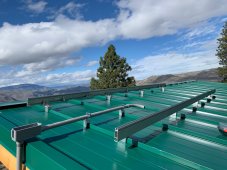
Sharing the panels, roof and view. It is overlooking the Columbia River and Lake Chelan. Now I just need to get my shunt wiring figured out :)
 

Attachments

  • solar1.jpg
    solar1.jpg
    301.8 KB · Views: 6
  • solar2.jpg
    solar2.jpg
    186.8 KB · Views: 6
  • solar3.jpg
    solar3.jpg
    537.9 KB · Views: 6
Thank you, this weekend I moved the red positive wire over to the first battery per your recommendation above. The fuse you see is the one that came in the Renogy kit (40A) that is inline from the charge controller to the first battery, if that is wrong I will change it, that was clear to me per their diagram (attached pic)


Or maybe I need a 2nd from the battery to the Inverter like you mentioned.

You do. Their diagram is for their charge controller, so they're not necessarily going to be accurate with the rest.

I did not get to move the shunt wiring around this weekend as I am still confused. I am going to try and draw up a diagram with what you are explaining, I don't do well with words I'm a visual hands on person. Thank you for your help and patience with me. -Mike

1619455875397.png

That's what they're telling you to do here:

1619455961652.png
 
You do. Their diagram is for their charge controller, so they're not necessarily going to be accurate with the rest.


View attachment 46815

That's what they're telling you to do here:

View attachment 46817
Snoobler, I made a diagram in Paintbrush (attached below) and I left out the connections that I am unsure of, would you be able to finish the connections? Picture reflects the positive cable I moved this last weekend from the 2nd battery +post to the 1st batter +post. I would be happy to send you some PayPal as a thank you for your time and patience with me lol just DM your email, thanks! -Mike ?
 

Attachments

  • Stuck.jpg
    Stuck.jpg
    33.5 KB · Views: 96
You saved the day! Everything working properly now, I connected as you told me to. Really really appreciate the help! Finally got time to head back out to the cabin. Showing charging now finally, woohoo! Sunny day too. Thanks Snoobler!
 

Attachments

  • BF65DA52-3B2F-4CE2-B2CA-7515C8B2EE86.jpeg
    BF65DA52-3B2F-4CE2-B2CA-7515C8B2EE86.jpeg
    96.8 KB · Views: 60
  • 3EBA3344-4A79-4AB5-AC2F-94DF2E61ED46.jpeg
    3EBA3344-4A79-4AB5-AC2F-94DF2E61ED46.jpeg
    91.8 KB · Views: 61
I will second the comment on super hero. I have been sniggling with the same issue. I did not want to move forward with wiring until I knew the answer. Today I will complete the wiring. It would be nice if Renogy just included the great diagram Snoobler drew. Life would have been so mcu easier.
 
Agree, and I’m glad this was of some help to you :) a little trick I learned on the screen if you hold the left arrow down for a few seconds it will illuminate the lcd screen on/off (some don’t want it on while they sleep etc) enjoy Steph!
 
Double posted with bad reception trying to figure out how to delete this comment lol
 
Last edited:
I read this the other day and it helped me get my shunt wired up and some other guys helping with my battery readout now! thanks snoobler
 
So just to be sure, I have a negative bus bar that gets all the negatives from my loads. I’m going to split the wire that connects my negative bus bar to my battery and put the shunt on there?
 
Hi, sorry to hijack this, but I am having an issue with my renogy 500a battery monitor not showing charge from my alternator.
I have two banks of batteries, starter and two leisure agm's, charged from my boat engine (plus solar and wind). I have my solar and wind going through the shunt, but my boat alternator goes directly to my starter battery. Once that is charged, the split relay then switches the charge to my leisure bank. Is there any way of showing the alternator charge on my renogy?
Many thanks in advance
The shunt would basically go on your B- terminal, and everything else would feed into the shunt. If the only thing connected to your battery negative terminal is the shunt, it will read all incoming and outgoing current from that battery. Anything between the shunt and the battery won't be read.
 
You saved the day! Everything working properly now, I connected as you told me to. Really really appreciate the help! Finally got time to head back out to the cabin. Showing charging now finally, woohoo! Sunny day too. Thanks Snoobler!
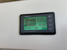
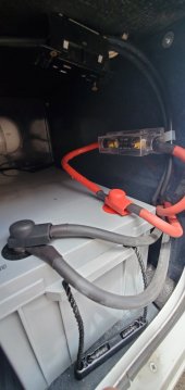
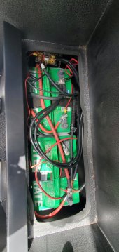
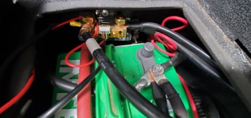
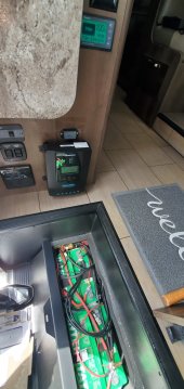
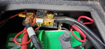
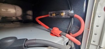
I am new to all this. I paid someone to wire it all up because I wasn't confident in doing it. It shows charging when the RV is running or generator, but nothing when the panels are working. The Rover shows it's pulling a charge but it's showing it's discharging when nothing is on.
I have 500W of solar, 200Ah battery, two 80Ah house batteries, 2000W renogy inverter, Rover MPPT, Battery Monitor, and I also have a go power automatic transfer switch near the breaker box.
I can't figure out what I need to do to fix it. I need help. I tried using the diagram and can't find where it's wrong.
I need it to to show charging when the panels are running.
 

Attachments

  • 20220614_113057.jpg
    20220614_113057.jpg
    72.8 KB · Views: 27
  • 20220614_113110.jpg
    20220614_113110.jpg
    123.3 KB · Views: 22
  • 20220614_113124.jpg
    20220614_113124.jpg
    213 KB · Views: 20
  • 20220614_113148.jpg
    20220614_113148.jpg
    120 KB · Views: 24
  • 20220614_113322.jpg
    20220614_113322.jpg
    404.2 KB · Views: 22
  • 20220614_113048.jpg
    20220614_113048.jpg
    194.1 KB · Views: 17
Back
Top