critical367
New Member
- Joined
- Dec 8, 2021
- Messages
- 10
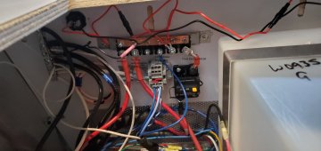
I installed a Renogy 30A DC-DC/MPPT combo and it works well. The one glitch is that it seems to draw around 2A when the ignition is off. The charging vehicle is a 2021 Subaru Ascent and I have the ignition wire connected to the Renogy using the 12V line in the 7-way connector. Of course, if I disconnect the trailer (I used Anderson plugs at the bumper) everything is fine and that is my work around, as long as I remember when we pull over for the night.
I have a case in with Renogy about this and they may send me a replacement unit. I will see if it works better, but wonder if anyone else has noticed this.
Thanks.
I have a case in with Renogy about this and they may send me a replacement unit. I will see if it works better, but wonder if anyone else has noticed this.
Thanks.