diy solar

diy solar

Resistance difference in C- and Positive cable matter?

Aajora

New Member
Joined
Jun 26, 2020
Messages
4
I'm terrible at explaining so bear with me here, thanks.

I built x4 lifepo4 105ah 12v batteries (already top balanced).
Each battery has a 100amp 4S BMS.
The four batteries will be wired in parallel to make a 12v 420Ah battery.
Those four batteries will then run to a positive and negnative main terminal.

Here's where my confusion starts.
As I understand, the C- wires on the BMS (two 10 gauge wires per BMS) will connect directly to the main negative battery terminal. Is this correct?

If that is correct, will the positive cable to the positive terminal need the same or similar resistance as the negative side (B-/C- bms wires, bus bar, bms)? Does this even matter?

I will wire all four batteries in parallel with 2/0 cable in a manner which draws current equally. It's what happens after that... getting my bank to one main positive and negative battery terminal in a way that will keep a balanced draw safely.
 
Last edited:
Length of a single wire from battery array positive to inverter, and single wire from battery array negative to inverter, don't have to be same as each other.

You have four batteries in parallel. The wire length (and length of each different gauge) that you encounter tracing from inverter negative through each battery to inverter positive, all have to be identical. So each battery sees same resistance, experiences equal discharge.

Got a sketch of your "four batteries in parallel with 2/0 cable in a manner which draws current equally"?
There are a couple ways to do it, just want to make sure you really did.
 
All the negative side resistance must be equal. All the positive side resistance must be equal. The negative side resistance does not need be equal to the positive side resistance.
 
All the negative side resistance must be equal. All the positive side resistance must be equal. The negative side resistance does not need be equal to the positive side resistance.
Sufficient but not (necessarily) necessary.

The "least wire" configuration to parallel four batteries has 3 wires on positive, 3 wires on negative, but the lengths various batteries see on negative side differ and the lengths they see on positive side differ.

That configuration is fine for lead-acid which don't require BMS, or for lithium with BMS per string. But if paralleling cells across multiple lithium strings so they share one BMS, what you describe is necessary.
 
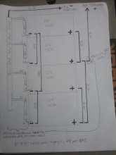
I'm not sure if the batteries will properly balance in parallel and discharge equally. Thanks for all the replies, I am really uncertain my BMS is even hooked up right to be honest so I have attached a drawing of what I am thinking.
Please don't hold back in mentioning what you believe to be common sense as I am working my way through this as a first timer with no electric experience.

20201113_121904.jpg
 
Good job on the positive side for balanced wires.
Negative side almost, until you connected that busbar and BMS something to each battery.
Single cable to the right terminal would have made it balanced.

Not sure, maybe the BMS thingy needs to move to between each negative terminal and the cables presently connected there?
But I'm not sure what your "BMS" does in that location. I might put a current sense shunt there.

Does each battery contain its own BMS for its own four cells? Maybe that's all that is needed.
If they were in series not parallel, then something external might be needed for further balancing.

I though you had 16 individual cells, might be wiring series/parallel as I've seen so a single 4 cell BMS balances all.
 
your right hedges, each battery has its own bms (4s), which reports voltage and balances individual cell health of their respective battery.
I suppose Im looking for confirmation that I wont kill my batteries or do irreparable damage to the cells. Ive researched and read everything but am unclear how to wire my 4 bms's in parallel, and mostly if the bms's are wired directly to the main negative terminal.

my issue is the bms's c- wires.. they seem to complicate the parallel wiring process.
 
I haven't used BMS, but assuming they are self-contained with disconnect, I would expect each to only connect to battery terminals and cell terminals. If they have an external shunt or disconnect, I would expect it to be between battery terminal and any cables, so it measures battery current and disconnects battery.

In series I do wonder how they would have to work together, but parallel they should each just look out for themselves. If one disconnects due to current the others get its load and proceed to disconnect two.

Sounds like you have a separate BMS and each battery has 4 cells, 5 places to connect wires? Got a schematic for the BMS? Or just parts with labels you can take a photo of?
 
I recommend doing the positive side using a buss bar like the negative side. Each battery connects to the buss bar with a short cable and the bus bar connects to the "positive terminal".
 
I recommend doing the positive side using a buss bar like the negative side. Each battery connects to the buss bar with a short cable and the bus bar connects to the "positive terminal".
With 5 holes in the busbar for four batteries and inverter, this could result in slightly different resistance paths for different batteries, slightly different discharge rates when high currents are drawn. I think there are a couple ways to balance it perfectly.

With batteries A, B, C, D and inverter I, connect as follows:

1) 5 holes in each: Positive bar, 5 holes with A, B, I, C, D. Negative bar, B, A, I, D, C

2) 3 holes in each, connect two battery cables top & bottom of bar to one bolt: (A & B), I, (C & D) for each bar
(That is what I did for one battery, 4 inverters, not that balancing is so critical, just more compact this way.)

3) 5 holes in a square bar, middle gets I, four corners get A, B, C, D

But a different perfectly balanced way without busbar is to use 3 cables on each of positive and negative exactly as he has done. Just don't connect "BMS (b-)" after that as shown. Instead battery negative cable to inverter goes to second battery from bottom, so connection similar to positive side.
 
Im going to assemble the bank as you jave instructed with the 5 hole bus bar. There wont be large draws as the inverter is only 2000 watts so for my purposes I think this is the best. thanks for helping me through this to hedges and the other responses.
 
But what about your BMS? Sounds like that is a separate unit, and the cells need to be wired to it for protection against over/under charge and over-current.

2000W at 12V? Maybe 90% efficient? That's 185A, so 45A per battery. Probably within BMS limits. Will it do 2x surge? 90A. (not including fault conditions.)
Have a fuse?
 
Back
Top