diy solar

diy solar

Reverse Polarity RV Plug on Bluetti/Ecoflow/Goalzero?? Is this a problem?

I don't think it's a problem at all. There is no exposed case on these units, and it's a floating system. It is only considered "reverse polarity" when using the other receptacles as a reference as to what "hot" and "neutral" is considered. It's alternating current though, so it doesn't matter. What does matter is if the reference potential of grounding conductors across ac outputs is bonded. And after testing this five seconds ago, they are. So I don't see any safety issue either.

Are you saying these products purposely have one receptacle that is wired differently than the others on the same device?

This is the normal way where there should be no potential difference (0V) and indeed almost no resistance between the Neutral and Ground and the Neutral and Ground are bonded (i.e. physically connected together) at the main source / breaker panel.

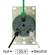
outlet.jpg
 
Has anyone connected an RV EMS device to see if it complains about the polarity?

My Progressive Industries EMS-PT30X does check for reverse polarity. It's a fault condition that will stop the flow of power.

• Reverse Polarity Protection: If AC power has a reverse polarity condition, the EMS will not allow power to the RV and the error code will read E 1.
 
My understanding is that the "neutral" conductor is determined by whatever is bonded to ground. So in the case of your ems pt30x, you will need to bond the ground and one hot conductor for it to be happy. Just like the Tesla charger.

One time I bonded the wrong hot conductor to my Teslas charger ground conductor, and it wouldn't charge. I had an error on the screen. So I tried the other hot conductor and it started working. I was bonding it manually with a extension cord, and it was connected to a older solar generator.

I just went out to the shop and tested every single outlet on the ac200 max:

The grounds have zero potential to any outlet plug that could be considered a neutral. Which means the grounds are isolated. I didn't find potential from any ground plug to any other outlet on the device. There may be some internal heatsink and negative bus that these grounds are connected to, but it is not bonded to anything that is leaving the unit. You could consider this unit a SAPS, and when used to supply a panel with an ATS, the ground may be used for code compliance.

Conversely, the ecoflow ac outlets have a small hole under each outlet where a ground prong is allowed to float. There is zero contact for the grounding conductor.
 
Just had a wildly speculative idea why the tt-30 polarity might be reversed on the solar generator in question.
Maybe they want to sell a "proprietary" bonding plug.
 
I just went out to the shop and tested every single outlet on the ac200 max:

The grounds have zero potential to any outlet plug that could be considered a neutral. Which means the grounds are isolated. I didn't find potential from any ground plug to any other outlet on the device. There may be some internal heatsink and negative bus that these grounds are connected to, but it is not bonded to anything that is leaving the unit. You could consider this unit a SAPS, and when used to supply a panel with an ATS, the ground may be used for code compliance.

Hi Will, your language is a bit confusing on this. For clarity:

Turn the unit on:

Are the voltages between all the round ground receptacles all zero?

If yes then what are the two AC voltages between the slots and the grounds for each receptacle?


1636935146277.png
A thought to keep in mind is that a surrounding metal chassis of any relevant load appliance is going to be connected to the ground. This can make a signal/noise/capacitive coupling difference to the internal design depending on how you deal with the power conductors where one is expected to be varying up and down to -170V and plus 170V and the other isn't varying wrt the chassis potential.

I would expect the grounds are all floating and if they aren't then they would be electrically connected to the neutrals (see above diagram). If they are connected to the neutral then you cannot feed a breaker panel that also has a ground-neutral 'bond' (i.e. electrical connection) as this ground-neutral connection is only permitted to happen at one location - not two.

if you measure 120V between the conventional neutral and ground then that's weird :)
 
Last edited:
Hi Will, your language is a bit confusing on this. For clarity:

Turn the unit on:

Are the voltages between all the round ground receptacles all zero?

If yes then what are the two AC voltages between the slots and the grounds for each receptacle?


View attachment 72285
A thought to keep in mind is that a surrounding metal chassis of any relevant load appliance is going to be connected to the ground. This can make a signal/noise/capacitive coupling difference to the internal design depending on how you deal with the power conductors where one is expected to be varying up and down to -170V and plus 170V and the other isn't varying wrt the chassis potential.

I would expect the grounds are all floating and if they aren't then they would be electrically connected to the neutrals (see above diagram). If they are connected to the neutral then you cannot feed a breaker panel that also has a ground-neutral 'bond' (i.e. electrical connection) as this ground-neutral connection is only permitted to happen at one location - not two.

if you measure 120V between the conventional neutral and ground then that's weird :)
Oh sure. The grounds are floating, and they are not connected to anything that someone would expect to be considered a neutral (from most plug wiring diagrams).

There is continuity between all ground receptacles.

But there is no potential between the ground receptacles and what people consider hot (even though it doesn't matter here). I was testing this to see if any outlet had a ground bonded to neutral (or what people would expect to be neutral based on plug schematics).

Sorry I was confusing with my words. Does that make sense?
 
Just had a wildly speculative idea why the tt-30 polarity might be reversed on the solar generator in question.
Maybe they want to sell a "proprietary" bonding plug.
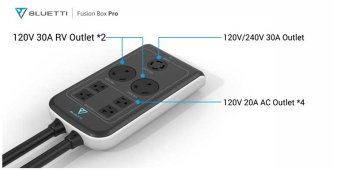
Oh good point! The ac300 actually uses the rv plug for 240V power box output:
bluetti-ac300-4.jpg
Maybe this is why the RV plug is wired this way?
 
Oh sure. The grounds are floating, and they are not connected to anything that someone would expect to be considered a neutral (from most plug wiring diagrams).

There is continuity between all ground receptacles.

But there is no potential between the ground receptacles and what people consider hot (even though it doesn't matter here). I was testing this to see if any outlet had a ground bonded to neutral (or what people would expect to be neutral based on plug schematics).

Sorry I was confusing with my words. Does that make sense?

I'll ask again :) What are the voltages, specifically, between the 'Neutral' port and ground and the 'Hot' port and ground for the 15A (actually 20A) receptacles?

And also what are these two measured voltages on the round 30A 'RV' plug receptacle?


1636937104197.png
outlet.jpg


PS that AC300 is the shiz! Split phase 240V! Would be cool to explore how that works.

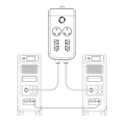
Ahh they use an AC sync cable where they will make the two AC waveforms 180deg out of phase.

1636938804859.png
 
Last edited:
I'll ask again :) What are the voltages, specifically, between the 'Neutral' port and ground and the 'Hot' port and ground for the 15A (actually 20A) receptacles?

And also what are these two measured voltages on the round 30A 'RV' plug receptacle?


View attachment 72288
outlet.jpg


PS that AC300 is the shiz! Split phase 240V! Would be cool to explore how that works.

Ahh they use an AC sync cable where they will make the two AC waveforms 180deg out of phase.

View attachment 72289
Neutral port and ground: 0V
Hot port and ground: 0V
Hot to neutral: 120V
 
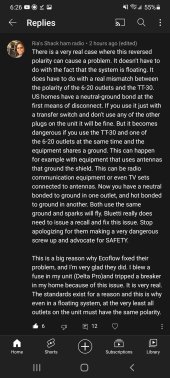
Check out this comment:
Screenshot_20211114-182654_YouTube.jpg

Ohhh ok, I see. So if you have a devices that bond neutral and ground (commenter references radio equipment) and you use both receptacles, there could be a problem.
 
Last edited:
Neutral port and ground: 0V
Hot port and ground: 0V
Hot to neutral: 120V
So is the ground port of the NEMA 5-20R even connected to anything at all? To the exposed metal of the unit? Or it is just a hole with no conductor at all? Same for the 30A outlet?
 
Neutral port and ground: 0V
Hot port and ground: 0V
Hot to neutral: 120V

Ok cool so there is no ground to anything bonding and the ground ports are floating relative to the two wire AC inverter output.

Now measure between the following according to the above diagrams.

Hot (30A) & Hot (20A)
Hot (30A) & Neu (20A)
Neu (30A) & Hot (20A)
Neu (30A) & Neu (20A)
 
So is the ground port of the NEMA 5-20R even connected to anything at all? To the exposed metal of the unit? Or it is just a hole with no conductor at all? Same for the 30A outlet?
All of the grounds are connected inside the unit. That's why connecting specialized equipment, such as some ham radios, to the RV plug and 6-20's at the same time will cause an issue. You will effectively have a ground neutral bond in one receptacle, and a ground hot bond in the other. And the ground connects them all together unfortunately. So there would be short from hot to neutral.

If the grounds were not bonded in the unit, there would be no issue.
 
Last edited:
All of the grounds are connected inside the unit. That's why connecting specialized equipment, such as some ham radios, to the RV plug and 6-20's will cause an issue. You will effectively have a ground neutral bond in one receptacle, and a ground hot in the other. And the ground connects them all together unfortunately.

But you just confirmed there is no G-N bond in any of receptacles. Nor a G-H bond in any of the receptacles.


Ahh I read Ria's post more carefully and she's referring the case where a G-N bond is made where it 'should' be made in one place at the load centre - where it should already be.
 
Last edited:
But you just confirmed there is no G-N bond in any of receptacles. Nor a G-H bond in any of the receptacles.

If these connections or 'bonds' are present on the load/equipment side - e.g. if there is load equipment that has downstream G-N bonds then this would make a mess but this is a huge no no and code violation for a number of other reasons too.
Yes exactly! That's why I said it's only specialized radio equipment. You're right.

It's just the only exception I found. Thought I should mention it anyways.
 
Let's have a look at these four AC voltages and get to the bottom of this....

Hot (30A) & Hot (20A)
Hot (30A) & Neu (20A)
Neu (30A) & Hot (20A)
Neu (30A) & Neu (20A)
 
Let's have a look at these four AC voltages and get to the bottom of this....

Hot (30A) & Hot (20A)
Hot (30A) & Neu (20A)
Neu (30A) & Hot (20A)
Neu (30A) & Neu (20A)
All 20A share the same hot/neutral. The 30A has the reversed.

So, 120V between hot 30A and hot 20A. Does that make sense?
 
All 20A share the same hot/neutral. The 30A has the reversed.

So, 120V between hot 30A and hot 20A. Does that make sense?

Yes, but the voltage measurements will confirm the situation fer sure if you can make them quickly. According H and N locations as defined by the diagrams above.
 
Back
Top