I am in the process of revamping the solar build on my trailer and as part of that have been looking at adding a few safety improvements. In particular, I installed an SAE solar port through the side of my trailer to support connecting a portable solar panel to augment the panels on my roof (two separate MPPTs). In researching these types of solar ports I am finding a sufficient number of reports about ambiguity regarding the polarity of these ports that I am thinking of putting in a reverse protection diode on the PV feed from the solar port, just in case someone plugs in a solar cable that is wired backwards from how the port is wired. Some MPPTs seem to have reverse protection built-in on their PV input, but the SmartSolar ones from Victron Energy do not as far as I can tell (probably to provide higher efficiency by avoiding a hard-wired voltage drop from the PV array due to a hard-wired diode in the circuit).
I will probably end up using the Roadmaster Hy-Power 790 diode as it has a built-in heatsink and spade connectors that make it easy to use as an inline diode on the PV feed. I have not been able to find any official specs from the manufacturer yet, but it would seem to be rated for 85A and I am assuming that it is a standard silicon diode with about a 0.7V forward voltage drop.
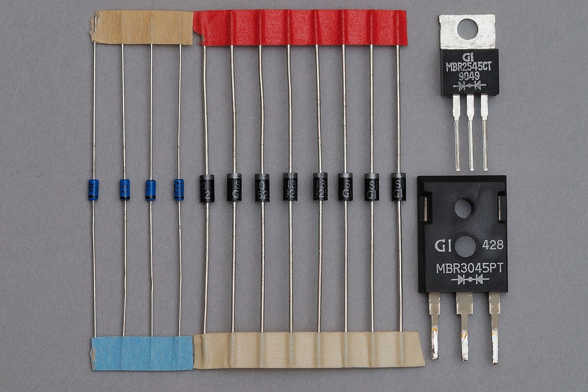
I started looking at Schottky diodes as they are supposed to have a lower forward voltage rating and the axial forms appear to be used as bypass diodes in most solar panels. Most literature indicates that Schottly diodes have a forward voltage drop of around 0.2V, which sounded nice in terms of reducing heat and power loss. But when I go looking for actual Schottky diodes that I can buy, the specs on those units indicate a forward voltage drop of 0.5V - very little difference from a standard silicon diode. It makes me wonder why bother with a Schottky diode if the gain is only 0.2V on the voltage drop as compared to a standard silicon diode. I'm looking at a system that would support an 18V 10A PV array - so a difference of 0.2V on the forward voltage drop only means a gain of 2W on the available power - hardly seems worth it.
In addition, it seems that these diodes do get rather hot: 50C to 60C from what I am reading. So I started to look at TO220 Schottky diodes as they are designed to be attached to a heatsink. However, the pin-out on the devices seems a bit awkward for an inline application. There are three pins on one end and a metal tab with a screw hole (to attach to the heatsink) on the other end. The tab and the center pin appear to be the cathode and the two outer pins appear to be the anode. In fact, the electrical diagrams that I can find seem to indicate that the TO220 is actually two parallel diodes with two separate anodes and a common cathode. So to wire this inline I think I would want to snip off the center pin and try to crimp the two outer pins to my 10AWG PV feed and then wire from the cathode tab to my MPPT. I guess it would work, but it seems a bit adhoc. Also, the diodes I've been looking at are rated for 15A to 20A which seems like a lot of current to pass through two pins - unless the pins are thicker than what the pictures convey.
Has anyone here worked with Schottky diodes and/or the TO220 form factor? Is the real-world forward voltage for Schottky diodes really 0.5V instead of 0.2V? Does that 2-pin anode design really work for 15A rated diodes?
I will probably end up using the Roadmaster Hy-Power 790 diode as it has a built-in heatsink and spade connectors that make it easy to use as an inline diode on the PV feed. I have not been able to find any official specs from the manufacturer yet, but it would seem to be rated for 85A and I am assuming that it is a standard silicon diode with about a 0.7V forward voltage drop.
I started looking at Schottky diodes as they are supposed to have a lower forward voltage rating and the axial forms appear to be used as bypass diodes in most solar panels. Most literature indicates that Schottly diodes have a forward voltage drop of around 0.2V, which sounded nice in terms of reducing heat and power loss. But when I go looking for actual Schottky diodes that I can buy, the specs on those units indicate a forward voltage drop of 0.5V - very little difference from a standard silicon diode. It makes me wonder why bother with a Schottky diode if the gain is only 0.2V on the voltage drop as compared to a standard silicon diode. I'm looking at a system that would support an 18V 10A PV array - so a difference of 0.2V on the forward voltage drop only means a gain of 2W on the available power - hardly seems worth it.
In addition, it seems that these diodes do get rather hot: 50C to 60C from what I am reading. So I started to look at TO220 Schottky diodes as they are designed to be attached to a heatsink. However, the pin-out on the devices seems a bit awkward for an inline application. There are three pins on one end and a metal tab with a screw hole (to attach to the heatsink) on the other end. The tab and the center pin appear to be the cathode and the two outer pins appear to be the anode. In fact, the electrical diagrams that I can find seem to indicate that the TO220 is actually two parallel diodes with two separate anodes and a common cathode. So to wire this inline I think I would want to snip off the center pin and try to crimp the two outer pins to my 10AWG PV feed and then wire from the cathode tab to my MPPT. I guess it would work, but it seems a bit adhoc. Also, the diodes I've been looking at are rated for 15A to 20A which seems like a lot of current to pass through two pins - unless the pins are thicker than what the pictures convey.
Has anyone here worked with Schottky diodes and/or the TO220 form factor? Is the real-world forward voltage for Schottky diodes really 0.5V instead of 0.2V? Does that 2-pin anode design really work for 15A rated diodes?