diy solar

diy solar

Revo II tripping breakers when 2 or more are in use

So I ended up buying a 25kva transformer. Ya it was a lot higher but I need something to get going.
If that's an isolation transformer, it will solve several issues with using these inverters.

With the center-tapped secondary being isolated, tie the center tap ("neutral") to the green ground wire of your house. The panel it feeds will have combined neutral and ground, just like your service entrance probably does. Anything connected to this new panel (including additional panels) will keep neutral and ground isolated.

1606789601430.png
 
If that's an isolation transformer, it will solve several issues with using these inverters.

With the center-tapped secondary being isolated, tie the center tap ("neutral") to the green ground wire of your house. The panel it feeds will have combined neutral and ground, just like your service entrance probably does. Anything connected to this new panel (including additional panels) will keep neutral and ground isolated.

View attachment 28984


So basically have the neutral and ground going to the same neutral/ ground block in the subpanel.
Then run one wire from the one hot leg to the transformer from the inverter and I assume just hook up either just 1 of the ground or neutral outputs or maybe both to the transformer?
 
Last edited:
Revo "L" and "N" AC output to to the two ends of primary winding. (depending on voltage configurability, primary may be a single winding, or two that can be connected series or parallel to support 240 or 120 input voltage.)

secondary windings should be center-tapped 120/240V. The ends go the the two busbars in a panel. The center goes to neutral bar of the panel. Ground wire from utility meter/panel and house goes to neutral of the panel. Neutral of the house does NOT go to this panel. In the panel, there is probably an optional green screw that bonds the neutral bar to enclosure of panel.

(Because transformer isolates, you re-establish bonding of neutral to ground in the panel it feeds.)

In the drawing I pasted above, primary on the left is wired to Revo "L" and "N", which are both hot.
The only thing going from secondary on right back to house wiring is the "ground" symbol.
 
I really want to know if the inverter has a 2-pole relay that disconnect both "L" and "N" during grid failure, or if it only disconnects "L".
I could trace the photos you posted to see it had a pushbutton breaker only for "L".
Can you locate the relay that it uses to disconnect from grid, see if it interrupts both or just one?

That is going to make all the difference in the world whether this inverter backfeeds the grid during a power failure or not.
Used as intended in "Europe" (and the rest of the world who started using utility electricity after we Americans invented it ;) ), with "N" being neutral, it should be fine. But fed with L1 & L2 and used for either 120V or even 240V appliances in the US, I can come up with multiple ways for it to electrocute a lineman if it doesn't isolate all poles.


(You'd think, with hydraulic power, the British would have invented the gasket. but no; they may have invented the Motorcycle, but the Japanese invented the gasket.)


Well I'm going to have to redo the wiring from the way I copied it from the Installer. I'm going to run 1 wire to the grounding bar to the ground terminal on the Revo. I'm going to run another wire from the grounding bar to the Neutral terminal on the Revo.
Now comes the tricky part. I need 240 current going into the Revo. Don't know how I'm going to do with that with split phase unless I some how wire the 2 legs together somehow coming from the 30 amp breaker lol

You're going to wire ground to the "Neutral" terminal on Revo, the one marked "N"?
Right now, one of the two hot "L1" or "L2" from utility grid goes to "N".
Can't do both.

Don't wire ground to the "N" terminal - ground and neutral only connect at one point, probably at your main utility breaker panel, near the meter.

You could wire neutral from utility panel to "N" terminal of Revo. Then you would need 240V to feed it. Not the 120/240 (with center tap grounded) coming from utility, but 240V relative to neutral. You could generate that with an isolated 240V in, 240V out transformer. Or, a 120/240V non-isolated auto-transformer (which will weight and cost half as much.)

But instead of this, I think you were on the right track with Revo's "N" and "L" connected to utility "L1" and "L2" from grid. Then using an isolation transformer on output of Revo to create and isolated 120/240 with center tap.
 
1) I'm not suggesting you throw them away, selling them on ebay to an overseas market were they are designed to be used would be my first choice
2) they are not "perfectly good functional" Revo units.
Please inform us your eBay sales name.

You plan to sell on eBay stuff what you consider not "perfectly good functional"???

That's BAD for karma!

Without holding them in your hands, how can you tell that they are not perfectly good functional???

Perhaps not best fit for USA, sure, besides this, nothing is wrong!

(Except the one defective unit, that is defective)
 
Don't wire ground to the "N" terminal - ground and neutral only connect at one point, probably at your main utility breaker panel, near the meter.
Indeed!!

Ground and Neutral are NOT the same thing.

To my understanding your transformer should fix all of this.
That is what it's for, yes?

It should have L and N for power in.
(And perhaps ground, not needed)

And should have L1 + L2 and N going out to the house.
Perhaps also ground, if you have 4 wire system)

If you need to do strange tricks like combine N with ground...
You got the wrong product.

They should never ever be combined in any configuration.
 
If you need to do strange tricks like combine N with ground...
You got the wrong product.

They should never ever be combined in any configuration.
Here in the US, we connect N to ground (at one point). But not for current flow (except in case of a fault); only one point not two so no path created for current.
That ensures voltage of hot relative to ground is defined.
It ensures neutral is at zero volts. Many appliances switch hot but not neutral. If neutral is zero volts, no voltage is present in the product beyond the power switch.
Most GFCI (except portable) interrupt hot but not neutral. If neutral had non-zero voltage, a shock hazard would remain.

After going through an isolation transformer, the secondary is floating. Neutral is not defined at zero volts relative to grounds. So we would call center tap of secondary "neutral" and tie it to ground. Same ground as the rest of the house in most cases. To a separate ground rod, I think, for a hospital system. (We have special electrical outlets, designated by a different color, with the ground pin wired separately and not connected to conduit or enclosure.)
 
If you need to do strange tricks like combine N with ground...
You got the wrong product.

They should never ever be combined in any configuration.
You must not be from the US. Your advice is 100% incorrect for the US market and will get someone seriously injured or killed.
 
@Hedges and @schmism :

What ever you people in the USA like to do AFTER the transformer, up to you.

Before the thrasformer you are working with NOT USA market product.

Like it can get people killed to wire incorrect for USA type, so does for the other side of the globe !!!

The advice to join neutral and ground will get people killed there!!!

As I have started before and will state again:
I know almost nothing about how you USA people like to combine 2 voltages with way to little wires and keep DC backwards compatibility for no good reason...

The rest of the globe doesn't make it complicated like that.
They just have L and N.
End of story. Nothing more, nothing less. 2 wires.
Optional a third wire, ground, for additional safety

And that is what we have here!!
A not complicated rest of the globe type of product.
That never ever ever should have neutral and ground connected.
NEVER.

What you like to do after you connect it to the transformer, connection L1 + N + ground + L2 or what ever...
Feel free.

For the Revo II, and only the Revo II (+ all other NOT USA style but rest of the globe style of electricity connection)
Never connect Neutral with ground.

That is absolutely good advice.
As it is NOT USA product, not USA wire type.
It doesn't have L1 and L2.
And ground is never ever to be used as any type of line for electricity, only for residual current device (aka safety breaker)
only for this from the Revo II.

for the people who don't know about residual current device,
Read about it on Wikipedia.

I don't know if USA have such life saving equipment, seems to be difficult to implement if you combine ground and neutral.....

But that is up to you folks to invent.


Talking about invention..
Newton did not invent gravity, he wrote about it, prove it exists
Benjamin Franklin didn't invent electricity, he prove its existence.
I do wonder who "invented" water!
(Or proven it's existence) :cool:
 
Last edited:
Hi, what settings do you use to charge your lifepo4?
I'm sorry, that's not an easy answer to make.

While it's really easy to give general advice, that will point you in the right direction (please look at the sticky from Will Prowse about charge profiles) it's a direction.

You will find the tweaks neseserry for your setup.

I have 3 * Revo II, and all 3 see slightly different battery voltage, what makes the charge profile for each unit slightly different.

For your system, you need to measure
Could you give me your charge profiles for the LifePO4?

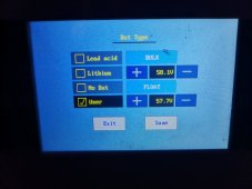
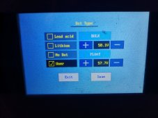
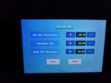
I have set mine in USER mode, Bulk 56V ( 3.5v cell ) and float at 54V ( 3.375V a cell ) . I have noticed that the charger doesn't stop bulk at the 56 but much higher, around 57. I had to reduce the bulk voltage to about 55.3/4 to get it to stop charging at 56.2. Do you have the same behavior?

In my inverter i dont have absorption mode. I believe yours don't have also?
Yes I can.

Or better yet, I'll give you the link to the sticky!!

Thread 'Recommended Charge Profile for DIY LiFePO4 Batteries *Sticky Post*' https://diysolarforum.com/threads/r...e-for-diy-lifepo4-batteries-sticky-post.5101/

Absorption and float are more or less the same.

I noticed difference between battery voltage and what the inverter reads, so that needs correction.

Further, for the Revo II, I also noticed the issue you're describing.

You need to use a setting sequence.
Standard is lead acid.
Going directly to user gives some "lead acid user mode" and Indeed doesn't stop always when you want.

If you first select LiFePO4, safe, exit menu.
(And just to be sure I reboot the Revo) after that select user, you get some "user Lithium mode" that listen more accurate.

The latest firmware also helps :)

Flashing is not a difficult process, does require some hardware to be purchased (about $10,-) and a computer with windows.

I'm not sure what made the thing work perfect now, the tweak with first selecting lithium and then user, or one of the firmware updates.

It works fine for me now and with these settings I have them 100% charged.
IMG_20210608_215046.jpg
 
Yes I can.

Or better yet, I'll give you the link to the sticky!!

Thread 'Recommended Charge Profile for DIY LiFePO4 Batteries *Sticky Post*' https://diysolarforum.com/threads/r...e-for-diy-lifepo4-batteries-sticky-post.5101/

Absorption and float are more or less the same.

I noticed difference between battery voltage and what the inverter reads, so that needs correction.

Further, for the Revo II, I also noticed the issue you're describing.

You need to use a setting sequence.
Standard is lead acid.
Going directly to user gives some "lead acid user mode" and Indeed doesn't stop always when you want.

If you first select LiFePO4, safe, exit menu.
(And just to be sure I reboot the Revo) after that select user, you get some "user Lithium mode" that listen more accurate.

The latest firmware also helps :)

Flashing is not a difficult process, does require some hardware to be purchased (about $10,-) and a computer with windows.

I'm not sure what made the thing work perfect now, the tweak with first selecting lithium and then user, or one of the firmware updates.

It works fine for me now and with these settings I have them 100% charged.
View attachment 52009
How did you update your Firmware? I asked for it at Sorotec but they refuse to give me. I have to pay for shipping to get a new controler board with the newest firmware.

Can you give me the steps for flashing, what software did you use and the firmware file and its version? my mppt version is 1.3.3, it doesnt show on the screen.

Also what procedure do you use to reboot the Revo?

Also, can you verify if you get Inv Comm timeout on your history?
 

Attachments

  • WhatsApp Image 2021-04-05 at 15.28.08.jpeg
    WhatsApp Image 2021-04-05 at 15.28.08.jpeg
    99.9 KB · Views: 7
Yes.
The controller board is secret.
I also don't have that firmware or tools to program.

Half or 2/3 of the "thinking" is done by the display unit.

That one is easy to program.
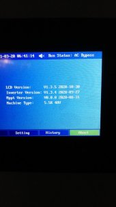
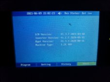
Latest display version is 1.3.7. who does include several languages.
I started with 1.3.1 :)

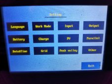
Some shots of the new display:

IMG_20210609_145907_copy_1000x750.jpgIMG_20210608_215046_copy_1000x750.jpgIMG_20210609_150013_copy_1000x750.jpgIMG_20210609_145918_copy_1000x750.jpgIMG_20210609_150056_copy_1000x750.jpg

"Manual" is attached.
You will need a J link
(Google on " j link jtag") any version will do.

If you are willing to try, please let me know.
There are additional steps I can share via PM.
 
Yes.
The controller board is secret.
I also don't have that firmware or tools to program.

Half or 2/3 of the "thinking" is done by the display unit.

That one is easy to program.
Latest display version is 1.3.7. who does include several languages.
I started with 1.3.1 :)

Some shots of the new display:

View attachment 52095View attachment 52096View attachment 52097View attachment 52098View attachment 52099

"Manual" is attached.
You will need a J link
(Google on " j link jtag") any version will do.

If you are willing to try, please let me know.
There are additional steps I can share via PM.
OK, the Mppt version is the same as mine. The inverter is older than mine.

PM me with the details and firmware. i give it a go. :). If you can show me what was the J-link you bought i appreciate it. I see many different ones online, like mini and other. The original one is 500dol.....

I don't see the "manual" attachment.
 
Last edited:
Back
Top