Hi Will,
Buy a relay rated for purpose. They are more expensive.")
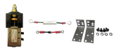
The good relays most of us use have back EMF suppression built in. They cost a little bit more.
I'm not sure this is true. Larger systems simply have higher complexity; there is no way around the physics.
Even with a huge relay, the inrush transients on large inverters can be so high as to make that expensive relay not last very long at all. Pre-charge circuitry is basically mandatory. It does not have to be expensive.
IMHO the only acceptable DC power relays are ones with a dual-coil design. You do get what you pay for.
Absolutely. FET arrays large enough to handle the transients possible in a large system would be prohibitively expensive. Note that Battery Protect is an asymmetric gate, too: one of them cannot stop current in both an HVD and LVD event.
The large inverters I'm familiar with don't have a relay, they just have a digital control and they power down the transformer. They don't fully isolate themselves on the DC side. That means they may still apply a load. In a LVD scenario, you may still have an overdraw event in this scenario.
If they did have a power relay, it would have all the challenges you mentioned above, and building one correctly would cost about the same. Most buyers wouldn't want that expense forced on them; better to have the design flexibility to do it elsewhere in the circuit.
A system that depends on control circuitry in the inverter creates a dependency: that inverter becomes the single point of control. For systems with multiple loads and chargers, it can be impractical to offload the emergency disconnect responsibility onto the many devices on the bus.
This is a good idea regardless of the other design concerns you've raised. 12V makes no sense in larger systems. But, I think this concern is mostly orthogonal to the other issues.
FET-based BMSes potentially have the same design issues we discussed above with external FET gates. Transients could pose an issue.
On the other hand, dividing and conquering is often a great design strategy. It is not necessarily inexpensive, though! There is a lot of voodoo out there about running multiple managed lithium batteries in parallel. Most of it is either wrong or straightforward to design around.
On balance, I think quality dual-coil contactors are the best all-around design choice for large systems. In some corner cases, other approaches might make sense, but on average I think the alternatives bring too much compromise to the table.
Some relays are not rated for continuous duty
Buy a relay rated for purpose. They are more expensive.
Relay kickback issue, which can destroy BMS if no fly back diode
The good relays most of us use have back EMF suppression built in. They cost a little bit more.
Adds unnecessary complexity
I'm not sure this is true. Larger systems simply have higher complexity; there is no way around the physics.
Capacitive load issues. If relay is sized properly, it shouldn't be an issue. But you need to make sure that relay is huge.
Even with a huge relay, the inrush transients on large inverters can be so high as to make that expensive relay not last very long at all. Pre-charge circuitry is basically mandatory. It does not have to be expensive.
Increased idle consumption
IMHO the only acceptable DC power relays are ones with a dual-coil design. You do get what you pay for.
And FET based switching mechanisms, such as Battery Protect, have their own problems:
Absolutely. FET arrays large enough to handle the transients possible in a large system would be prohibitively expensive. Note that Battery Protect is an asymmetric gate, too: one of them cannot stop current in both an HVD and LVD event.
Using a high quality inverter with relay input. This way you will never need to worry about switching large currents. Use a BMS or other form of logic control system to control the inverter.
The large inverters I'm familiar with don't have a relay, they just have a digital control and they power down the transformer. They don't fully isolate themselves on the DC side. That means they may still apply a load. In a LVD scenario, you may still have an overdraw event in this scenario.
If they did have a power relay, it would have all the challenges you mentioned above, and building one correctly would cost about the same.
Most buyers wouldn't want that expense forced on them; better to have the design flexibility to do it elsewhere in the circuit.A system that depends on control circuitry in the inverter creates a dependency: that inverter becomes the single point of control. For systems with multiple loads and chargers, it can be impractical to offload the emergency disconnect responsibility onto the many devices on the bus.
Increase the voltage of your battery bank to reduce the current requirement of your inverter, then run a standard 100-300A BMS. A 100A 48v BMS is small and can easily power a 4500W inverter. A 300A 48V BMS is a bit larger, but can run a 13,500W inverter.
This is a good idea regardless of the other design concerns you've raised. 12V makes no sense in larger systems. But, I think this concern is mostly orthogonal to the other issues.
Run BMS in parallel. But! Not in a single bank. That can cause other problems. You will need to make multiple battery banks with their own BMS, then parallel the battery banks together for a larger current capacity.
FET-based BMSes potentially have the same design issues we discussed above with external FET gates. Transients could pose an issue.
On the other hand, dividing and conquering is often a great design strategy. It is not necessarily inexpensive, though! There is a lot of voodoo out there about running multiple managed lithium batteries in parallel. Most of it is either wrong or straightforward to design around.
On balance, I think quality dual-coil contactors are the best all-around design choice for large systems. In some corner cases, other approaches might make sense, but on average I think the alternatives bring too much compromise to the table.