diy solar

diy solar

RV Electrical Diagram Feedback

Spire

New Member
Joined
Nov 9, 2022
Messages
10
Hey guys,

I'm working on putting together an RV electrical system, and I was hoping to get some feedback on the preliminary diagram that I made.
I did a lot of research as I went along, but there are some things I'm not 100% sure about. If someone could take a quick look for issues, that would be awesome!

Also, I have a few specific questions.
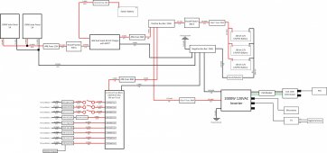
  • Is the 250A main battery fuse adequate for the combined 12V loads and inverter load? I totaled up the amperage, and I'm right under 250A. This would also be assuming that all the components are on and running at full load simultaneously. Would I be better off going up to 300A? This would require getting higher rated bus bars and possibly cables larger than 2/0.
  • Are there any locations where an additional shutoff switch would be beneficial?
  • Are there any locations where a resettable breaker would be a better choice over a fuse?
Thanks!


electrical diagram.jpg
 
The mini AC circuit doesn't look right.
What amperage does the ac require and at what voltage?
 
The fusing in your system needs modification .

There is no point in having a fuse in the solar panel feed , the panel current can never exceed the panels SC current, around 11 amps for two 100 watt panels.

The fuses between the positive buss bar and, 12 volt fuse box, DC/MPPT charger, inverter, need to be as close as practical to the buss bar, not 2 or 3 feet away. Distribution fuse blocks are an alternative and combine buss bar and fuse holder,

You have a GFCI on the shore power input but this will not give protection on the Inverter AC output.
 
The mini AC circuit doesn't look right.
What amperage does the ac require and at what voltage?
Just double checked and the AC unit itself is 240W at 24V. The 12V to 24V converter is rated for 280W max.
I used the converter wattage / 12V to arrive at 25A (I rounded up)

Did I get something wrong here?

Thanks for taking a look BTW!
 
The fusing in your system needs modification .

There is no point in having a fuse in the solar panel feed , the panel current can never exceed the panels SC current, around 11 amps for two 100 watt panels.

The fuses between the positive buss bar and, 12 volt fuse box, DC/MPPT charger, inverter, need to be as close as practical to the buss bar, not 2 or 3 feet away. Distribution fuse blocks are an alternative and combine buss bar and fuse holder,

You have a GFCI on the shore power input but this will not give protection on the Inverter AC output.
Interesting, thanks for the info. I put a fuse between the solar panels and the DC/MPPT charger because it shows one in the manual. Not sure why it shows that.

I'm planning to put the fuses right next to the positive bus bar. I over-estimated the lengths just to make sure I was safe with the wire gauge.

Regarding the fuse for the DC/MPPT charger, should that be as close to the charger as possible or as close to the positive bus bar? My limited knowledge leads me to think I would want it closer to the charger since the current is flowing from there to the bus bar.
 
Just double checked and the AC unit itself is 240W at 24V. The 12V to 24V converter is rated for 280W max.
I used the converter wattage / 12V to arrive at 25A (I rounded up)

Did I get something wrong here?
I'm guessing that fuse block has a max fuse size of 30 amps per branch.
Also guessing it uses automotive style fuses and that the terminals are secured using #10 machine screws.
The largest wire that you can reasonably land on a branch circuit position is 10 awg.

240 watts at 10 volts low cutoff = 24 amps
24 amps / .8 conversion efficiency = 30 amps (boost converters usually have lousy efficiency)
30 amps / .8 fuse headroom = 37.5 amps

I think you will have to run 8 awg with a 50 amp fuse off the main busbars.

Also if this is the air conditioner, be prepared to be underwhelmed.
 
Last edited:
Fuses protect against excessive current flow under faults, the battery via the positive buss bar, has the ability to deliver a higher current than than the cable can tollerate. Thus to protect the DC/MPPT and its supply cable, fuse at the buss bar.
 
Last edited:
I'm guessing that fuse block has a max fuse size of 30 amps per branch.
Also guessing it uses automotive style fuses and that the terminals are secured using #10 machine screws.
The largest wire that you can reasonably land on a branch circuit position is 10 awg.

240 watts at 10 volts low cutoff = 24 amps
24 amps / .8 conversion efficiency = 30 amps (boost converters usually have lousy efficiency)
30 amps / .8 fuse headroom = 37.5 amps

I think you will have to run 8 awg with a 50 amp fuse off the main busbars.

Also if this is the air conditioner, be prepared to be underwhelmed.
Thanks, that's very helpful! Totally makes sense.
I moved the circuit off the fuse block to the bus bars with a 50 amp fuse and 8 awg wire.
 
Which DC-DC/MPPT are you planning to use?

Diagonal connection of batteries is not optimal. See the link below for better solutions. Look at the Battery Wiring section.

 
Fuses protect against excessive current flow under faults, the battery via the positive buss bar, has the ability to deliver a higher current than than the cable can tollerate. Thus to protect the DC/MPPT and its supply cable, fuse at the buss bar.
Hi!
This is one of my doubts.
Given that both car's alternator + battery and house battery may drive higher current than the cable can tolerate, should there be a fuse in each cable extremity?
(As in, one exiting the positive busbar and one exiting the car's battery to DC/DC charge controller)

Thanks in advance!
 
Back
Top