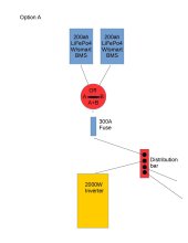
The system also includes 400 watts worth of solar, with a Renogy DCC50S DC-DC charger with MPPT, as well as a Progressive Dynamics PD9260 converter. I like the idea of the dual bank A/B switch as it lets me isolate and run off a single battery if something goes wonky with one while traveling in the RV. I don't really like the idea of the switch before the fuse, but given the physical setup I don't see much of a way to do it without adding wire length. The A/B switch (which is a Blue Sea 9001E rated at 350a continuous), BMS is set to shut down on overcurrent at 110A on each battery. Wiring from each battery to the A/B switch, and to the negative stud by the switch are a 2 AWG 3 ft long each, these run through a 4 individual holes in a plywood bulkhead from the cabinet where the batteries are located to the placement of the switch and stud. From the output of the switch, and the negative stud 4/0 will be ran to either the inverter or the positive and negative bus bars.
Figure A would require approximately 14-15 ft of 4/0 from the switch output lug / Y point negative stud, Figure B would only require about 7-8 ft of 4/0 and the existing 1/0 currently connecting the inverter to the bus bars could be re-utilized to backfeed the distribution bars.
I know the more proper way is figure A, but is it worth deviating from standard to shorten the circuit by 7-8 ft of 4/0?
Thanks Ike
p.s I know 4/0 is probably overkill, but I have a couple of pieces of it on hand (a 9 ft piece of black and an 11 ft piece of red), other choice on hand is 1/0, and about half a dozen 3ft sections of 2AWG welding cable with lugs already on them (4 of which are used in this layout +/- initial leads from the batteries.