diy solar

diy solar

RV schematics/diagram specfic to UK code

Solarfun4jim

Solar seduced :-)
Joined
Sep 22, 2019
Messages
743
Location
Sunny Scotland
Hi folks, i'm looking specifically to UK van/motorhome dwellers to provide a schematic or rough diagram of their layout, with specific reference to meeting UK code on grounding/earthing, chassis ground etc.
Some appear to have no 'units' bonded to chassis, only the negative busbar. It all seems to get more confusing when 'occasionally/non permanently' connected to grid power through to the inverter/charger units. This also seems to vary considerably from country to country. Any experienced UK based folks that can give a difinitive answer as to the safest way to connect everything up. Assume that 99% of time there will be no grid connection in my example.
Is all bonding done via the negative busbar? Other than the 'straight through' power of the grid connect to the inverter /charger (which carries its earth connection from the grid power source, what other earthing cables are necessary? Bond solar panel frames to chassis? Everything else through negative connection to busbar?
When no grid connection, does this still provide reliable safety for the inverted 240vac to the consumer panel, with no true earth connection.
Hear so much conflicting info, cant get my head into a positive place....and with electricity, i need to be there.
Any help offered would be most graciously recieved. A layman trying to read up on the IEE Wiring Regulations (17th edition) 2008 etc, simply gets bogged down. :-(
 
Last edited:
Hiya,

Always return to your negative bus bar and avoid using the vehicle chassis as the manufacturer uses that as a return for the vehicle electrics. Plus having to remove paint to make a secure connection will eventually lead to corrosion in that area.

If your using DC and/or AC then having localised fuse boxes in each area with that fuse box having a positive and negative returning to your bus bars is far easier than a huge spaghetti mess of having every single electrical component fused in-line and return to the bus bar.

I drew a bad sketch for you. sketch1583581556838.png
 
With solar, the positive and negative need to go to you MPPT (solar charge controller) before then going to the bus bars. Don't use the chassis for the negative.

It's perfectly safe to have 230v from the inverter as long as it's all wired and fused properly and you've used the right guage cables.

I'll try and draw you a better diagram on my laptop later.
 
Last edited:
With solar, the positive and negative need to go to you MPPT (solar charge controller) before then going to the bus bars. Don't use the chassis for the negative.

It's perfectly safe to have 230v from the inverter as long as it's all wired and fused properly and you've used the right guage cables.

I'll try and draw you a better diagram on my laptop later.
Thanks EllaBella, i have a good idea about the layout of the various components, it was simply if there was a conflict of code with regards to the inverter/charger, sometimes being grid powered thus earthed through grid supply connection but other times, there would be none. I'd be using a 48v battery bank and simply wondered if it necessary to ground the negative bus bar to the chassis. I could stop galvanic corrosion pretty much using a silver washer between the metal surfaces and then hammerite over the top to seal everything. However, if it is strictly not necessary, then i wont be doing it. I'm assuming all RCD's, RCBO's, ELCB's etc etc all work perfectly fine, as opposed to fuses simply blowing when the amps rise?
Is this what they call a 'floating' ground, where everthing is simply connected to the negative bus bar....i take it this is possible because the RV is isolated on tyres?
Cheers (y)

ps on another note, is it better to ground the solar panel frames to the chassis or is this also superfluous? RV roof material would be insulator as opposed to metal bodywork.
 
Last edited:
This guys van build has got lots of good information.
Suggest you watch all of it including the later videos that identify the things he would have done differently in hindsight.
 
Last edited:
@smoothJoey I watched all of Greg Virgoe's videos, they were very helpful as I was unsure about putting LPG into my future van build. I loved many of the ideas he had and his workmanship was brilliant.

@Solarfun4jim I'm looking to put 48v into my next van build too along with a 5kw hybrid inverter charger. Going to build the 48v battery myself too using CALB lifepo4 cells that Will Prowse has done many helpful videos on. For £1200 I can get x16 3.7v 100ah cells giving me something like 5.12kwh.

I'm my previous builds I have never had fuses blow and everything worked fine, but it was on a small 12v system in my Jeep mini camper. Had a single leisure battery, single solar panel, small MPPT, small inverter to charge my laptop and printer so I could print out paperwork for work.

I wouldn't ground the solar to the chassis at all, it could cause a short to another part of the system if it comes into contact with the chassis. But if your roof is insulated from the rest of the chassis then there would be no completed circuit from your solar to your MPPT unless you ran a cable from the inside of your roof to your MPPT hence why it would just be easier to run a negative and a positive through a port in your roof to your MPPT/Hybrid Inverter Charger, it would give less resistance through pure copper cable than running it through the roof medium.
Thanks (y)
 
@smoothJoey Due to my work being so seasonal I move to different locations a lot, so I've decided to just to do a big van conversion to have my home on wheels and exactly the way I want it, rather than only choosing job that have accommodation which limits me to what contracts I can take (renting isn't an ideal option). As I may be in countries that have either fewer hours of sunshine or overcast weather, I wanted a large enough battery bank to power everything for several days with out having to drive to charge from the alternator or having to find grid power to plug into. As I'll also have my friend living with me a lot of the time I'll also need to factor in the extra power storage for all her electrics too. I'm looking to put in a small washing machine, microwave, TV, desktop pc, gaming console, AC ect... Plus we'll be using hair dryers, laptops, charging phones ect...

So my system will hopefully have over 1kw of solar on the roof, 5kwh of battery power and a 5kw hybrid inverter charger. I'm going to leave areas to be expandable in the future, so I could put in more batteries or solar if needed.

In regards to hybrid, I mean an all in one solar and grid inverter charger, so if I'm connected to grid it will charge my batteries as well as supply 230v AC but also charge from solar. Like the Victron Easy Solar but I'll get a different brand that's a bit cheaper. They also act as a UPS and will switch from grid power to battery/solar if there's a grid power cut.

I'm looking to get an Iveco Daily 4100L H3 which has about 5.1m x 1.7m of cargo space, so I can fit in two single beds, a shower/toilet, cargo area for our sailing/paddle board/windsurf kit, kitchen area and lounge. From drawing it all out, we both should be able to live full time comfortably in this space.
 
Last edited:
Thanks for explaining hybrid.
I meant why such big inverter?
Do you have a load in the vicinity of 5KW?
 
Thanks for explaining hybrid.
I meant why such big inverter?
Do you have a load in the vicinity of 5KW?
Sorry, you replied while I was editing to include all my power use.

If we happen to be working in a hot country, I want to be able to run AC with out having to run the engine, so I'm hoping to have enough insulation, solar and battery power to have a small AC unit running when needed.

Plus a 5kw hybrid inverter is not a lot more than a 3kw, so if I pay a bit extra, I can have some redundancy.
 
Last edited:
EllaBella, any plans to charge your 48v battery bank from the alternator? Plenty of 12v-12v systems about, but 48v seems to be a bit convoluted to me. Just asking, as i'm planning a 48v system myself. With Solar pv being the only charging source whilst wild camping, the added bonus of alternator charging whilst driving between stopping points is attractive.
 
Last edited:
Unfortunately with a 48v battery it seems to be impossible to charge from the alternator, even victron's buck boost only goes to 24v. I haven't found a way to do it yet. Some people talked about having a second alternator and some how bridging the two but everyone seem a bit unsure.

My main reason for having 48v was to run a powerful inverter more efficiently, so maybe a way around it would be to have a separate 12v battery bank then you could run all your 12v electrics off that only, have the alternator charge the 12v battery bank and also use a 48v DC to 12v DC converter to charge it from solar too?
 
Can someone tell me why you wouldn't run the negative to the chassis? if there are some connections or bolts allready existing why not hook up to them? makes live and connection stuff easier in my opinion.
 
Unfortunately with a 48v battery it seems to be impossible to charge from the alternator, even victron's buck boost only goes to 24v. I haven't found a way to do it yet. Some people talked about having a second alternator and some how bridging the two but everyone seem a bit unsure.

My main reason for having 48v was to run a powerful inverter more efficiently, so maybe a way around it would be to have a separate 12v battery bank then you could run all your 12v electrics off that only, have the alternator charge the 12v battery bank and also use a 48v DC to 12v DC converter to charge it from solar too?
Yes, that's what i was coming around to...a seperate 12v battery, gives me more capacity anyways and makes handling the small 12 dc loads so much simpler. (y)
Just curious Ella, are you an electrician or just knowledge you have picked up along the way?
 
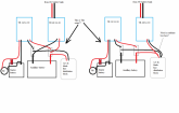
If taking the idea of an 'additional' 12v battery pack further, whereby it had two power sources, 1/ victron orion TR 48/12-30A from 48v bank & 2/ victron orion TR smart 12/12-30 from the alternator/engine battery.
My question is, would you connect the output from 1/ TR 48/12-30 to the aux 12v battery bank along with the TR 12/12-30 or would you direct the output through the DC blade fuse distribution block?
I presume keeping the more critical/always on loads on the 12v side and luxuries on the 48v/inverter side.

Would i need any battery protects or is that all handled by the victron units themselves?


Which setup.png
 
Unfortunately with a 48v battery it seems to be impossible to charge from the alternator, even victron's buck boost only goes to 24v. I haven't found a way to do it yet. Some people talked about having a second alternator and some how bridging the two but everyone seem a bit unsure.

My main reason for having 48v was to run a powerful inverter more efficiently, so maybe a way around it would be to have a separate 12v battery bank then you could run all your 12v electrics off that only, have the alternator charge the 12v battery bank and also use a 48v DC to 12v DC converter to charge it from solar too?

Hi,
I'm facing the same issue and wonder: would this do the job? https://www.sterling-power-usa.com/SterlingPower12volt-to-48volt-batterytobatterycharger.aspx
 
Yes, that's what i was coming around to...a seperate 12v battery, gives me more capacity anyways and makes handling the small 12 dc loads so much simpler. (y)
Just curious Ella, are you an electrician or just knowledge you have picked up along the way?
Just picked it up along the way, same with fixing cars, building computers, doing DIY, just hate paying extra when I can do it myself.
 
Back
Top