There's no difference between 2 serial vs. 2 parallel panels in a mppt controller. They will output the same wattage.
I've already mentioned you will see about 5% more power from a mppt controller vs. a pwm controller. It doesn't matter if the mppt panels are in parallel or series.
Regarding cables going into controller: A mppt controller is sensitive to cable losses. A pwm controller is to-an-extent not sensitive to cable losses. If you want an efficient mppt system then you must keep cable losses (from panel to controller) at 1%. You can have 3% cable losses when using a pwm controller and it won't affect output power.
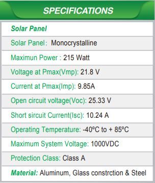
Panels usually don't output rated power because this rating is accomplished in lab conditions: 25C temperature and 1000 W/m irradiance. You won't see that in real life. 50C to 75C and 800 W/m is typical.
I've already mentioned you will see about 5% more power from a mppt controller vs. a pwm controller. It doesn't matter if the mppt panels are in parallel or series.
Regarding cables going into controller: A mppt controller is sensitive to cable losses. A pwm controller is to-an-extent not sensitive to cable losses. If you want an efficient mppt system then you must keep cable losses (from panel to controller) at 1%. You can have 3% cable losses when using a pwm controller and it won't affect output power.
Panels usually don't output rated power because this rating is accomplished in lab conditions: 25C temperature and 1000 W/m irradiance. You won't see that in real life. 50C to 75C and 800 W/m is typical.

")