diy solar

diy solar

Ryobi Zero-Turn Mower SLA to LiFePo4 Conversion - (Updated - Build Complete With Pics!)

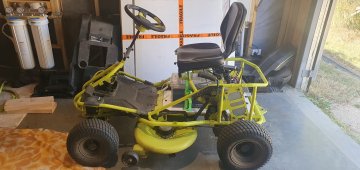
I guess we are all converting our mowers, huh. I bought a new Ryobi Zero Turn 42" mower, just to convert to Lithium Iron Phosphate.

I thought I was surely not the first and did a google search and found this right up. What a help.,

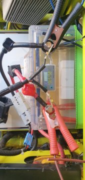
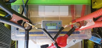
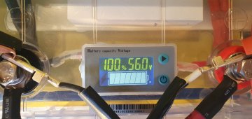
I replaced my 4-75 ah batteries with Weize 12V 100 AH batteries that received an excellent review from Will Prowse. They were an easy drop in replacement. Weize batteries at Amazon

1669942053718.png
1669942074311.png

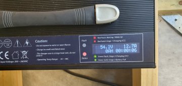
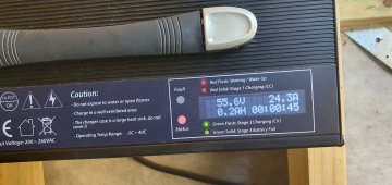
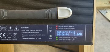
I purchased an AC to DC 48 volt charger from Signature Solar. I will be connecting it to the mower batteries directly, and foregoing the standard charging port that I purchased from Amazon. When my solar charging system is in place in the trailer, I will use a DC to DC charger instead of the AC to DC Charger, I have not found 1 that I like yet.

I am starting an All-Electric, All-Solar Powered lawn service in Chattanooga, TN. I will be charging all of my mowers and tools with 12-100 watt solar panels on the roof of my enclosed trailer, from Amazon as well.

I purchased the inverter and 2 batteries to store the power during the day and recharge the tools overnight from Signature Solar as well.

Here is a rendering of my trailer that is currently being wrapped. Yes, I did change out the photos of shots of my actual equipment. Until I get a sponsor, I am using the Ryobi zero turn and backpack blower, all of my other equipment is Kobalt 80 volt including 2 self propelled mowers, 2 string trimmers, 1 blower, 1 hedge trimmer, 1 pole saw.
1669941808285.png

So here is the question....

The batteries from my Ryobi Zero Turn (4-75ah SLA batteries) have 2.1 hours on them from cutting my lawn and a few of the neighbors. I should never need them and want to sell them to recoup some of my expenses. What do you think they are worth on Marketplace or eBay?

I suppose the charger will never be needed again either, and I hear that they are in short supply. Any suggestions on a price for that as well?

Thanks for any input anyone has on if and how to sell the batteries and charger!
 
Thank you for the reply. I appreciate all the info I can get. It's the off-season now so I have a few months to prepare for spring. I'll be making the swap out over the next few months.


I know very little about these types of things (all things being electric)... Can you explain this in more detail? Apologies as I'm learning ;) Where did you get your 200 ohm 50W resistor (amazon)? I know what a single pole switch is thankfully ;)

i.e.
battery side of the the main contactor ---> switch <--- [200 ohm 50W resistor] ---> load side of contactor

where is the battery side and where is the load side of contactor? (photos?)

I bought a 12V 15A charger and charged each battery up to 100% individually then connected all 4 of them in parallel. I'm not sure how long to leave them like this, but I read that this needs to be done to "balance" the bms's between the batteries.

I know how to wire them into series, but will then need a 48V charger. How do you charge yours? What make/model did you get?
Anyone else able to provide any insight... I have a few months before its mowing season again and I'd like to make the conversion! TY.

I have in my basement 4x CHINS 12V LiFePO4 100 AH wired together in parallel. I read that this needs to be done prior to putting them in series for balancing. I charged each one up to 100% then connected them together in parallel. They've been sitting there for a few weeks now...I'm not sure how long to leave them like this, but I'm not ready yet to swap the batteries.

I did purchase the Signature Solar 48V 5A charger. I don't need to charge any faster than 5A and I only have a single 20A circuit for my garage.

I can make the conversion anytime, but want to make sure I'm doing this correctly.
 
Last edited:
Anyone else able to provide any insight... I have a few months before its mowing season again and I'd like to make the conversion! TY.

I have in my basement 4x CHINS 12V LiFePO4 100 AH wired together in parallel. I read that this needs to be done prior to putting them in series for balancing. I charged each one up to 100% then connected them together in parallel. They've been sitting there for a few weeks now...I'm not sure how long to leave them like this, but I'm not ready yet to swap the batteries.

I did purchase the Signature Solar 48V 5A charger. I don't need to charge any faster than 5A and I only have a single 20A circuit for my garage.

I can make the conversion anytime, but want to make sure I'm doing this correctly.
A 20A circuit should be able to power at least a 40A charger at 48V
 
I am starting an All-Electric, All-Solar Powered lawn service in Chattanooga, TN. I will be charging all of my mowers and tools with 12-100 watt solar panels on the roof of my enclosed trailer, from Amazon as well.
I appreciate the enthusiasm for solar, but how confident is your math on this? Are you truly planning on *all* the power coming from this, or just supplemental + good marketing?

I am curious, as I have tossed about this idea a few times and the numbers just dont work out for a full day of mowing and trimming given average solar, the output loss from flat mounting and inconsistent parking, cloudy days, etc.
Do you have extra equipment batteries onboard to cover for shortages?
Are you DC to DC charging from a high output alternator to the trailer?

Obviously an 8 hour day wont involve 8 hours of mower operation of course, but you will eventually have a healthy number of clients and end up killing your batteries within one shift.

That's a lot of power and the short duration to plug the stuff in from one house to the next wont allow for a lot of charging without having spare batteries for the equipment itself to swap - which I assume is how you will do it, but did not mention as the case.

However.

I would expect something like 4 to 4.5 hours of equivalent average sunlight down there, which gives you 5.4kwh daily of solar. Maybe closer to 6 hours during the summer, giving you something like 7.2kwh per day on average.With perfect full sun conditions you can charge the mower in your post, plus maybe a trimmer and blower, about once per day with very little leftover power, and realistically you will consume far more than that, so supplemental power will quickly become extremely important for you.


Without looking at your solar panel layout, I would question if its as maximized as possible given the larger 400+ watt panels available - though I understand taking the easier, smaller route up front.

Not that I think its a bad idea, I love this, you just need to make sure you can cover for the crappy cloudy days and days when you have a bunch of lawns, and ideally a method that doesn't look bad to the types of clients that a "solar powered lawncare" service would attract.


Perhaps an additional large panel on a ladder rack above your tow vehicle? That would help considerably, offering you potentially 400+ watts more, and plugging in at night to charge your extra batteries and easy-peasy.
 
Last edited:
Swappable large economical battery bank. PV at home charges one bank while you carry the other in the truck to recharge smaller, more expensive batteries for tools.

The more practical, affordable, "Green" solution (although harder to explain to the Great Unwashed) is GT PV at home, recharge portable batteries in truck at night, use those batteries to recharge tool batteries on the go during the day.

A Ford Lightning or other EV with utility outlets would be ideal. But DIY battery more economical. Throw a PV panel on the roof as an advertising sign.
 
Greetings everyone. I hope everyone had a great holiday season.


This weekend I decided to start my conversion.

I picked up the following items to treat this as the least invasive drop-in replacement solution:


Batteries:

Ampere Time 12V 100Ah LiFePO4 Lithium Battery, 4000+ Deep Cycle Lithium Iron Phosphate Battery, Built-in 100A BMS (https://www.amazon.com/dp/B0BCKHFR26?psc=1&ref=ppx_yo2ov_dt_b_product_details)


Battery Indicator:

CAMWAY Battery Monitor 8-120V 0-500A Voltmeter Ammeter Voltage Current Meter Backlight
(https://www.amazon.com/gp/product/B088RG27LS/ref=ppx_yo_dt_b_search_asin_title?ie=UTF8&psc=1)


Charger:

ULTRA FAST 48V 15 AMP DAKOTA LITHIUM LIFEPO4 BATTERY CHARGER
(https://dakotalithium.com/product/4...4-battery-charger-for-lithium-iron-batteries/)

Victron Energy Blue Smart IP65 12-Volt 5 amp Battery Charger (Bluetooth)
(https://www.amazon.com/dp/B07TLCT7X7?psc=1&ref=ppx_yo2ov_dt_b_product_details)

Note that I used the Victron for individually charging my new LiFePo batteries since it came so highly recommended. However, the charger automatically installed a new firmware update which I discovered gave me some very wonky results when trying to charge in the Li-ion setting taking far longer than it should have or never entering the proper phases. I would normally have to reset my history and reconnect the plugs to get it to register. It seems like a problem with the firmware when I looked up the issue online. Use this charger with caution.

Cables:

Anderson Power Products SB50 Connector Kit, 50 Amps, Gray Housing, w/ 10 12 AWG, 6319 (1 Pair)
(https://www.amazon.com/dp/B07CHD4JCK?psc=1&ref=ppx_yo2ov_dt_b_product_details)

Drive-up EZGO RXV 48 Volt Charger Receptacle with Wire / 3-Pin Triangle Charger Plug Handle EZGO Charging Port OEM#604321 611219 602529 Golf Cart
(https://www.amazon.com/dp/B082S9BH7R?psc=1&ref=ppx_yo2ov_dt_b_product_details)

Work done:
I was able to remove my old Leoch batteries and drop in the new Ampere Time batteries. I reused all existing cabling. One observation with the four 12V 100Ah batteries is that they seem to be a bit taller than the original Leoch. Using the plastic Ryobi battery terminal cover plates it is just a bit too tall to use the long hold-down screw with the washer and lock washer installed. I was able to install the bolt without the washers. I may need to look into a longer bolt.

I validated all of my batteries were charged and balanced to about 53.3V before and after the install.

When I went to turn on the mower I heard the relay click but no power showed on the original meter. Measuring the voltage at the original charge port showed low to no voltage. I disconnected the main Anderson plug to the batteries and tested the voltage to the battery which was reading 53.3V. I feared I had somehow nuked my charger port again. I reconnected the main Anderson plug again and remeasured the voltage at the charger port. The charger read the normal 53.3V. Whew!

I then turned the mower on again, heard the relay click…again no power. Disconnecting and reconnecting the battery returned to proper voltage.

I then decided to leave the multimeter probes for measuring voltage connected to the charge port so that I could observe the voltage change when I turned the key on. When I did this…the mower came on and read 100% on the meter!

I disconnected my multimeter and was able to turn the mower on and off without issue (at least so far). I’m not exactly sure if the mulitmeter being connected was a fluke, or if it provided just enough momentary resistance that it allowed the circuits to properly turn on the electronics. I still haven’t tried mowing or other heavy loads but the lights, blades, beepers, etc…are all functioning. Maybe someone can explain what the connected multimeter in DC voltage testing mode actually did to allow the mower to turn on. Regardless, I’ll take that win!

Now I’m onto the next step of installing the new power gauge. I followed the advice of many on this forum that have used the Camway battery monitor off of Amazon. The sampler block on this monitor is enormous.

I opened up the control panel and removed the old battery indicator. This indicator has a single plug with three wires (two green and one black). There isn’t a lot of slack in the existing wiring, so I wasn’t trying to cut connectors in case I needed to hook up the original indicator. Also, there are no labels for what the different wires are used for on the original indicator.

Where I’m scratching my head a bit is how people hooked up the new Camway monitor since its instructions show cables going back to the battery. The existing wiring is also using green and black vs red and black. After some multimeter voltage testing it seems like existing wiring has the green wires as the battery pos and the black wire is hooked up to battery negative.

I guess, my first question is if anyone has a photo of how they did the wiring connections to the new camway monitor from the existing Ryboi wiring? See attached pictures.

If not:

Do I need to connect both green wires from the legacy Ryobi indicator to the new Camway or just one?

Do I just connect a single black wire from legacy Ryobi wiring to the B- connector on the Camway?

No wires will come from the P- connector on the camway?

How did folks mount/secure the Camway sensor block to their mower?


Any advice and/or pictures on how the Camway indicator was wired and secured into your conversion would be greatly appreciated.

Ryobi Battery indicator - B.png
 
Greetings everyone. I hope everyone had a great holiday season.


This weekend I decided to start my conversion.

I picked up the following items to treat this as the least invasive drop-in replacement solution:


Batteries:

Ampere Time 12V 100Ah LiFePO4 Lithium Battery, 4000+ Deep Cycle Lithium Iron Phosphate Battery, Built-in 100A BMS (https://www.amazon.com/dp/B0BCKHFR26?psc=1&ref=ppx_yo2ov_dt_b_product_details)


Battery Indicator:

CAMWAY Battery Monitor 8-120V 0-500A Voltmeter Ammeter Voltage Current Meter Backlight
(https://www.amazon.com/gp/product/B088RG27LS/ref=ppx_yo_dt_b_search_asin_title?ie=UTF8&psc=1)


Charger:

ULTRA FAST 48V 15 AMP DAKOTA LITHIUM LIFEPO4 BATTERY CHARGER
(https://dakotalithium.com/product/4...4-battery-charger-for-lithium-iron-batteries/)

Victron Energy Blue Smart IP65 12-Volt 5 amp Battery Charger (Bluetooth)
(https://www.amazon.com/dp/B07TLCT7X7?psc=1&ref=ppx_yo2ov_dt_b_product_details)

Note that I used the Victron for individually charging my new LiFePo batteries since it came so highly recommended. However, the charger automatically installed a new firmware update which I discovered gave me some very wonky results when trying to charge in the Li-ion setting taking far longer than it should have or never entering the proper phases. I would normally have to reset my history and reconnect the plugs to get it to register. It seems like a problem with the firmware when I looked up the issue online. Use this charger with caution.

Cables:

Anderson Power Products SB50 Connector Kit, 50 Amps, Gray Housing, w/ 10 12 AWG, 6319 (1 Pair)
(https://www.amazon.com/dp/B07CHD4JCK?psc=1&ref=ppx_yo2ov_dt_b_product_details)

Drive-up EZGO RXV 48 Volt Charger Receptacle with Wire / 3-Pin Triangle Charger Plug Handle EZGO Charging Port OEM#604321 611219 602529 Golf Cart
(https://www.amazon.com/dp/B082S9BH7R?psc=1&ref=ppx_yo2ov_dt_b_product_details)

Work done:
I was able to remove my old Leoch batteries and drop in the new Ampere Time batteries. I reused all existing cabling. One observation with the four 12V 100Ah batteries is that they seem to be a bit taller than the original Leoch. Using the plastic Ryobi battery terminal cover plates it is just a bit too tall to use the long hold-down screw with the washer and lock washer installed. I was able to install the bolt without the washers. I may need to look into a longer bolt.

I validated all of my batteries were charged and balanced to about 53.3V before and after the install.

When I went to turn on the mower I heard the relay click but no power showed on the original meter. Measuring the voltage at the original charge port showed low to no voltage. I disconnected the main Anderson plug to the batteries and tested the voltage to the battery which was reading 53.3V. I feared I had somehow nuked my charger port again. I reconnected the main Anderson plug again and remeasured the voltage at the charger port. The charger read the normal 53.3V. Whew!

I then turned the mower on again, heard the relay click…again no power. Disconnecting and reconnecting the battery returned to proper voltage.

I then decided to leave the multimeter probes for measuring voltage connected to the charge port so that I could observe the voltage change when I turned the key on. When I did this…the mower came on and read 100% on the meter!

I disconnected my multimeter and was able to turn the mower on and off without issue (at least so far). I’m not exactly sure if the mulitmeter being connected was a fluke, or if it provided just enough momentary resistance that it allowed the circuits to properly turn on the electronics. I still haven’t tried mowing or other heavy loads but the lights, blades, beepers, etc…are all functioning. Maybe someone can explain what the connected multimeter in DC voltage testing mode actually did to allow the mower to turn on. Regardless, I’ll take that win!

Now I’m onto the next step of installing the new power gauge. I followed the advice of many on this forum that have used the Camway battery monitor off of Amazon. The sampler block on this monitor is enormous.

I opened up the control panel and removed the old battery indicator. This indicator has a single plug with three wires (two green and one black). There isn’t a lot of slack in the existing wiring, so I wasn’t trying to cut connectors in case I needed to hook up the original indicator. Also, there are no labels for what the different wires are used for on the original indicator.

Where I’m scratching my head a bit is how people hooked up the new Camway monitor since its instructions show cables going back to the battery. The existing wiring is also using green and black vs red and black. After some multimeter voltage testing it seems like existing wiring has the green wires as the battery pos and the black wire is hooked up to battery negative.

I guess, my first question is if anyone has a photo of how they did the wiring connections to the new camway monitor from the existing Ryboi wiring? See attached pictures.

If not:

Do I need to connect both green wires from the legacy Ryobi indicator to the new Camway or just one? UPDATE: Both green wires need to be connected to both B+ screws on the Camway. 18-22awg wires should be sufficient for connecting into the pins of the existing indicator plug.
Do I just connect a single black wire from legacy Ryobi wiring to the B- connector on the Camway? UPDATE: I can confirm that you only need to have a single 18-22awg wire from the existing plug to the small Camway B- terminal.

No wires will come from the P- connector on the camway? UPDATE: Doesn't seem to be required.

How did folks mount/secure the Camway sensor block to their mower? This is still an open question that would be great to see how people mounted this. In theory it could be wired to hang below the indicator, but I would prefer it to not move around. I'm thinking of drilling some holes through the side of of the plastic housing next to the seat into the area below the indicator and then use bolts to mount the new Camway sensor block to the inside of that cavity just below the indicator. If anyone has a better suggestion, I'm all ears!

1673299578404.png
 
You will want to hook the shunt up to the battery. I don't think the wires from the old meter will work. I took the plastic piece off the shunt and bolted B- directly to the negative threaded terminal and P- to the negative load cable. Positive wire for the shunt I hooked up directly to battery. This keeps the meter on all the time but I have mine hooked up to solar so it doesn't matter to me.

The new gauge is bigger than the original one so you will need to make the opening bigger in the metal holder. If you have the right tools it is pretty easy, if you don't it is a pain. Otherwise you could mount it somewhere else.

Thanks Buff and Supervstech. Hooking it up to the battery seemed to make the most sense when installed to a solar solution. However, for this mower application I wasn't looking for the meter to be on the whole time. There also seems to be somekind of lockout logic built into the wiring for the old meter on the mower. If I leave any of the wires disconnected the mower wont turn on. As soon as I ran a wire from black on the old meter wiring to the B- on the shunt and two wires from the green wires on the old meter wiring to the two B+ terminals on the shunt everything turned on and worked. The new camway monitor display lit up, seemed to read the voltage and current in realtime. I could calibrate all the settings on the monitor. Maybe it isn't actually working even though the monitor seems to be reporting using the wiring to the old monitor.

As far as mounting the shunt, I guess you answered that part when you said you removed the plastic and screwed directly to the battery terminal. When it comes to mounting the monitor display I agree that it took some work. I used a large step drill to widen the hole a bit more and a metal file to finish off the edge. No issues on that part. I was mainly figuring out where to put the shunt if I was able to reuse the old monitor wiring for the task.

If you did this conversion with the new meter did you have any issues with mower powering on if the old wiring wasn't used?

If I were to reuse the existing wiring would I need to add another line to the P- side like this?
1673368747216.png

I would be interested to hear what other people have done in regards to this Camway monitor. Again, trying to go with the least invasive "drop in" approach to minimize wiring changes. Note that I'm using the RY48ZTR100 100ah zero turn model mower which has a different monitor than the older 30" RM380 mower with the steering wheel.

I did find an interesting video on Youtube for a RM380 mower:
1673385316798.png
1673385331701.png
1673385274395.png

Does this jive with the recommedation on how to install for the zero turn model? If so, on the ZTR what did folks do with the old monitor plug/wires? Are they just left disconnected with no further action? I couldn't turn the mower on if the old monitor wires were not connected.
 
Last edited:
Ah, yeah I have an older RM480 38" non-zero turn and leaving the connector unplugged from the old meter works for it. Perhaps they changed the wiring with the new zero-turn ones or they were different to begin with. Hopefully someone with a newer zero-turn has an answer!
 
Ah, yeah I have an older RM480 38" non-zero turn and leaving the connector unplugged from the old meter works for it. Perhaps they changed the wiring with the new zero-turn ones or they were different to begin with. Hopefully someone with a newer zero-turn has an answer!
Thanks for confirming. I've already found several differences between what you need to do to make the RM480 work vs the RY48ZTR. I'm hoping someone else on the forum can chime in on what they did for the ZTR models when installing the Camway (AiLi) monitor to save me from pulling out my hair. Trial and error has gotten me so far, but trying to avoid that "broken clock is right twice a day" situation by thinking I have something right and it blowing up later.
 
New update. I "completed" my conversion this weekend. As a recap, I have the zero turn 100ah model (RY48ZTR100). I used 4 "drop in" Ampere Time 12v 100ah batteries, and the Camway/AiLi Battery Monitor for the new batteries. I'm using the Dakota Lithium 48v 15A battery charger hooked up to a BL Link mechanical timer.

I say "completed" in quotes because the system works but it isn't 100%. Not sure what can be done to improve the install and experience. From my earlier posts, when I had just converted the batteries and still had the original Ryobi monitor in place the relay would clunk when the key was turned on, battery showed full charge but the rest of the power system wasn't registering any volts. I would have to disconnect and reconnect the main battery anderson plug to "reset" the system. Eventually I had my multimeter probes to test voltage at the charge port when I turned it on and it worked.

Subsequently I hooked the new Camway monitor up to the pins on the plug used to hookup the Ryobi monitor. Once I had all wires "jumped to the new monitor shunt everything turned on and seemed to be reading proper voltage. Even though this wasn't the way the shunt was supposed to be wired it seemed to work. However, per the feedback from Buff and Supervstech I installed the Camway/AiLi shunt to the battery. Interestingly enough, when I did this I was able to turn the mower on without having anything connected to the old monitor plug which was not my past experience getting the unit turned on. The system seemed to turn on and off without any issues, so I was happy...for a moment.

I went back about 30-40 min later. I could see the new monitor was still reading the proper battery information (since it is always on after connecting directly to the battery). I went to turn the unit on and the monitor readout started to breakdown like you see on a low battery and then turned off completely. The batteries were not reading any meaningful voltage vs a full charge. It seemed like the battery BMS had kicked in and shut the power down to the batteries. I hooked up my Dakota charger to the charge port and turned it on momentarily. This woke the batteries back up and the monitor was again showing the proper information. I was also able to turn the mower on after this "primer charge".

I did a full yard mow without any issues (yes I can still mow in Florida in the winter even if the grass isn't growing as quickly). I left the mower for about 20-30 min to go do some edging and blowing, and when I came back I was able to turn the mower on again. However, when I tried to re-engage the blades the blade motors did a slow partial start and stopped. It was like they lacked the juice to spin up. I was able to put the mower into drive and after I drove around a moment I was able to spin up the blades.

So the system works and starts normally as long as I don't leave the mower sit "off" for more than 25min. If it sits longer, it seems to trip the BMS when I start the system up which requires me to use my charger to almost act as a "jump start". Since I normally mow non-stop it isn't too bad to just "prime" the system with a battery charge before I start it up, but it is pretty annoying. I don't know why the BMS would be tripping under these startups after the mower is sitting off for more than 30min. I don't want to potentially be damaging any of the mower controller electronics.

I've seen other people on the forum talking about installing "pre-charge" circuit, and Hedges normally suggests some kind of inline resistor like a light bulb. I'd rather not go the lightbulb route, but I'm wondering if anyone else has had a similar experience with their conversion and what they may have done to resolve it. I'm not sure if this is an issue specific with the AmpereTime batteries and its BMS. I'm suspecting there is a momentary current rush on startup that is tripping the battery BMS. However, the system seems to start fine once it has been started once. That seems to indicate the system needed the capacitors on the mower charge controller to be charged up enough and if it sits idle for more than 30 min the capacitors drain. I have seen references to people with golf carts needing a "pre-charge" circuit. I have seen references to a solenoid, resistor, and diode being used in a precharge circuit. I'm curious if anyone has had to go this route (if they think this is my problem) and has any links to parts I can quickly assemble designed for this purpose?

Thanks!
 
Hi All,
Thanks for your knowledge, effort and expertise; I've been marvelling at you all from afar. I've run into a problem and was wondering if anyone could help. A little bit of background... I've installed a 48V 100ah battery into a RM480e mower. I had a quick ride around and it seemed to work fine. When I tried to charge the battery through the charging port with a 48V 25A LiFePo4 charger it didn't work. I was able to do a charge by attaching the pins directly to the battery terminals temporarily with alligator clips. The battery charged to 100%, as indicated on the charger as well as the battery's indicator, but after a couple of hours of remaining parked and not in use the battery's indicator read 87%. I have just recharged the battery by the same means after a small amount of use and the battery quickly rose back up to 100% on the battery's indicator after the charger put 2ah into the battery.

I've attached photos of the charger and battery at 6 seconds, 45 seconds and 6 minutes.

As you can see, it seems to have gone from 85 to 100% in 45 seconds. It is now 10 minutes or so since I took those photos and the battery now reads 94% and is falling.

My questions are:
- Is my battery being fully charged?
- Why does the SoC indicated on the battery fall without use?
- What do I need to do to get the charging port working?
- The battery specifications say charge voltage is 56.8 - 58.4v. Is it a problem that it is going beyond this range?
- Is the voltage difference between the charger and battery a problem?

I really am a bit out of my depth - thank you for whatever help you can give!

Battery https://voltx.com.au/products/voltx-48v-100ah-premium
Charger
(I'm in Australia so these are Australian sites)
 

Attachments

  • 20230119_160846.jpg
    20230119_160846.jpg
    312.1 KB · Views: 28
  • 20230119_160819.jpg
    20230119_160819.jpg
    136.2 KB · Views: 19
  • 20230119_160925.jpg
    20230119_160925.jpg
    338 KB · Views: 19
  • 20230119_160937.jpg
    20230119_160937.jpg
    352.4 KB · Views: 19
  • 20230119_161448.jpg
    20230119_161448.jpg
    300.3 KB · Views: 17
  • 20230119_161456.jpg
    20230119_161456.jpg
    275.2 KB · Views: 25
  • 20230119_153345.jpg
    20230119_153345.jpg
    332 KB · Views: 27
Ok, so I think the battery capacity indicator is just inaccurate because using volts to ascertain state of charge is an inexact science...
 
another option is to control a disconnect relay and wire the motor directly to the relay. Then you dont have to have a high current BMS to pass 200+ amps to the motor. and instead just monitor battery voltage and trigger the relay when H/L Vco.

This is what http://www.electrodacus.com/ does. However they only support 8s at the moment. Its my understanding that some of the Daly BMS can also be used to trigger the right kinds of relays for this kind of setup.
I’m a little late to this thread but qucc (recommended) and chargery (not recommended) use external relays.
 
How is your VoltX battery performing? I've just ordered the same one for my Ryobi Zero Turn.
It's a well built battery at a good price. The indicator on the front is a bit of a gimmick, just don't expect it to give an accurate reading. Apart from that, I think it's a good drop in solution. Having said that, I don't have the equipment to run all the tests.

I've actually decided I'd like to go through the process of building a battery though, so will probably go with 160Ah cells rather than the voltX battery.
 
Back
Top